Troubleshooting the Wire Feed System
Accurately troubleshooting problems with the delivery of the welding wire to the weld pool and the current to the wire when they arise or, better yet, avoiding them before they arise, is crucial to maximizing the benefits that these processes offer.
Posted: August 16, 2011
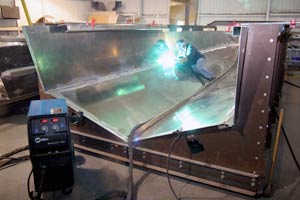


MIG (GMAW) and flux-cored (FCAW) welding, commonly referred to as “wire welding,” offer the potential for significant gains in productivity compared to stick welding. However, the wire feed system uses a more complicated mechanical system than the others to deliver the welding wire to the weld pool and the current to the wire, resulting in more potential problems in the functioning of the welding equipment.
Accurately troubleshooting these problems when they arise or, better yet, avoiding them before they arise, is crucial to maximizing the benefits that these processes offer.
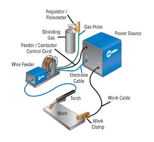
For troubleshooting purposes, the wire welding system can be divided into three distinct categories based on function – wire delivery, gas supply and electricity transmission. Failure within any of these systems will result in sub-optimal welding performance, including reduced productivity and increased downtime for reworking bad welds.
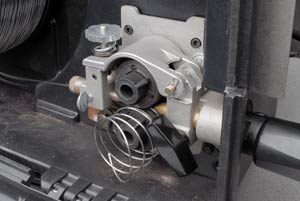
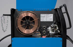
WIRE DELIVERY
Regardless if you are using one-pound spools, large drums, or larger coils of wire, the mechanical feedability of the wire plays an important role in determining arc quality and weldability. You should begin troubleshooting the system by ensuring the wire is not obstructed anywhere along its path from the spool tension to the contact tip and everywhere in-between.
Hub Tension
It is important not to over-tighten the hub tension, which allows the spool of wire to turn. On a large drum of wire, this function may be served by a mechanism that traces around the spool. The hub tension is simply a means to keep the wire from de-coiling off of the spool when wire feeding stops. This should be just tight enough to keep the wire from de-coiling when you stop feeding a full spool at maximum wire feed speed. Over-tightening this will force the drive motor to work harder just to get the wire off of the spool and will lead to welding problems.
Check Drive Roll Pressure
Drive roll pressure is a very common problem in wire welding. Too loose and you have no wire feeding into the puddle. Too tight and you can crush the wire and flake off the coating, deform the wire, wear out the rolls, and damage the motor.
Flaked coating will cause these small flakes to enter the liner, further limiting the simple feedability of the wire to the puddle. Deformed wire will wear grooves into the contact tip limiting electrical conductivity and also causing poor feedability. Wear out the grooved surfaces of the rolls and you have poor friction to feed the wire properly. Over-tightened drive roll tension causes all of these problems in addition to placing excessive pressure on the drive shaft that could wear out a gear box or drive motor by misaligning it.
There is no cut-and-dry answer as to the exact pressure needed to ensure proper drive roll pressure. Drive roll tension should be adjusted so that it is not too tight, but not too loose. Start with the drive roll pressure very loose. Increase the pressure only until it is very difficult to stop the wire from feeding out of the contact tip. Use a pliers or block of wood to try and stop the wire from feeding. Go perhaps one-half of a turn beyond this point. When the wire is actually stopped, the drive rolls should spin on the wire and no bird nesting should occur.
Check Drive Roll Alignment
The drive rolls can be adjusted side-to-side to ensure they are in line with the inlet guide to the GMAW gun.
Check Inlet Guides
The inlet guides should be of the proper size for the wire used. They should not have grooves in them – often caused by misalignment or improper size.
Check Liner Condition
The gun liner should be the proper size for the wire being used and should also be clean and free of dust and debris. Over-tensioned wire will flake off and place excessive particles into the liner, clogging it up. Using special wire lubricants can also cause the wire to become ‘wet’ and dust can collect on the wire dragging it into the liner as well.
Wire manufacturers have already properly prepared the surface of the wire for maximum feedability and adding or even subtracting that can affect the weld quality. If you insist on using something to “lubricate” or “wipe off” the wire before it goes into the system, a cotton cloth with a clothes pin would be best so that there is no contamination of the wire and dust cannot collect on a ‘wet” surface. Liners are wear items and should be replaced on a regular schedule.
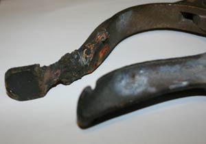
Contact Tip Condition
Many times feeding problems can be fixed by replacing the contact tip. The contact tip can get clogged up from spatter or from touching it to the weld puddle. If the wire is wearing grooves into the contact tip you need to check your drive roll tension.
GAS SUPPLY
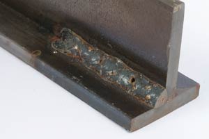
In MIG and gas-shielded flux-cored arc welding, a number of problems can occur that interfere with the delivery of shielding gas to the weld pool, leading to porosity, excess spatter, an unstable arc and other defects. The smallest pinhole in a gas hose can act like a carburetor and draw in air, contaminating the weld. Here are several steps that should be taken to troubleshoot suspected shielding gas problems:
Check the Regulator/Flow Meter
The glass tube-and-ball type of flow gauge can be used as an indicator of gas leaks. If the ball does not drop to the bottom of the gauge when not welding, it is an indicator that gas is still flowing, indicating a leak. If a dial-type regulator/flow meter is used, a leak can be detected by applying a soap and water solution to all hoses and connections. Escaping gas will cause bubbles to form in the soap and water solution at the point of the leak.
Remember, gas connections and hoses downstream from the gas valve have to be checked with the gas flowing. Use the purge function during this process. Also, turning off the cylinder and watching the high pressure side slowly fall will also indicate that there is a leak in the system.
Check Gas Flow
More is not necessarily better here. Gas flow rates will typically be between 30 and 50 CFH (cubic feet per hour). Flow rates lower than this can provide inadequate shielding, resulting in porosity. Flow rates higher that this can cause problems where the surrounding atmosphere can be drawn into the shielding gas, providing a contaminated shielding gas supply, also resulting in porosity.
Check Gun Condition
Check the O-rings found on the end of the welding gun where it attaches to the wire feeder guide. If one or both O-rings are missing, cracked, gouged or worn, shielding gas can leak out or the atmosphere can be drawn in, with both instances resulting in reduced welding performance.
Check the gas ports found in the diffuser, and on some consumables brands, in the nozzle. These holes can also become clogged with spatter and restrict shielding gas flow to the weld pool. These components should be checked several times throughout the day, even if a shielding gas problem isn’t suspected.
Inside the gun cable is a hose that contains both the liner and the shielding gas. This hose can also fail from overuse and holes can be created inside of the cable, through which gas can escape and you would never see it. This problem is mostly caused by using too small of a gun for the amperage being used to weld and from the constant flexing of the gun during use.
The inside diameter of the welding gun nozzle can also have an impact on shielding gas delivery. If the nozzle diameter is too small and gas flow is set too high, a venturi-type of effect can occur, drawing in the atmosphere and contaminating the gas supply. Also, if the nozzle is too large in diameter or the contact tip extends too far from the end of the nozzle or if the contact tip-to-work distance is too great, shielding gas coverage will be impacted.
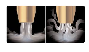
ELECTRICITY TRANSMISSION
Without good electrical flow between the power source, wire feeder, lead cable and work cable, you could experience a variety of problems, including a sputtering arc, excessive spatter and reduced equipment longevity. The best way to avoid these problems, or troubleshoot them when they occur, is to verify that all of the electrical connections between the welding components are tight and secure.
Resistance is the “unknown” welding variable and the largest cause of inconsistencies in any welding system. The MIG gun is constantly bent and twisted during normal use. This, combined with heat from the welding application, breaks down the copper in the gun over time. If you find yourself turning up your machine from the day when everything was new and correct to achieve the same result, you likely have a resistance issue.
All electrical connections for the welding cables and work cables need to be checked. All connections need to be clean and tight. No paint, rust or washers of any type should be between the copper lugs and the connection surfaces. Check to ensure that all weld cable-to-lug crimps are tight.
A good indication of a poor electrical connection is heat. After the cell has been welding for a while, check all connection points and welding cables for heat. If either the connections or cables feel hot, it is a likely indication that there is too much electrical resistance in the circuit. This could be caused by loose or faulty connections, cables that are too small for the application or an internal break in a cable. A cable that is too small for the application will likely be hot along its entire length, where as a break in the cable will result in a specific point along the cable becoming hot.
The contact tip is another common source of interruptions in the electrical current. The weld current needs to pass through this connection and into the wire, so it must be held tightly to the diffuser and it must make good contact with the welding wire. An indication of a loose connection is a discolored contact tip where it makes its connection to the diffuser. If this occurs, replace the tip with a new one and ensure that it is tightly fastened to the diffuser.
Although, it would take an entire book to list all of the problems that could potentially arise in wire welding and their possible causes, following the guidelines above should put you well on your way to renewed welding success.
Subscribe to learn the latest in manufacturing.
Subscribe to learn the latest in manufacturing.
Industry News