10 Common TIG Problems and Solutions
Here are some descriptions of common TIG mistakes and basic tips on how to prevent these errors from happening.
Posted: September 12, 2011


Gas tungsten arc welding (GTAW), also known as TIG, is arguably the most difficult process to learn. This article contains descriptions of common TIG mistakes and basic tips on how to prevent these errors from happening.
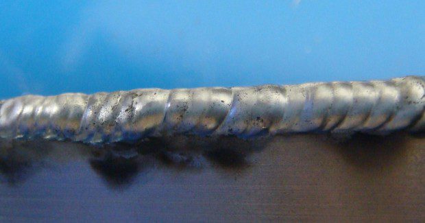
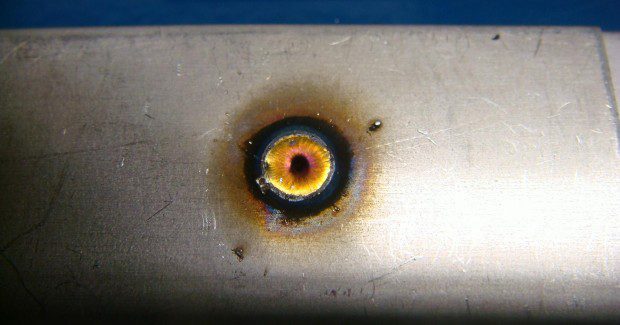
(1) POOR GAS COVERAGE LEADS TO CONTAMINATION
Throughout this discussion, please reference the application photos to the right beginning with Figure 1. Weld contamination can occur when shielding gas is not turned on, there is too little or too much gas shielding or the gas is blown away. To troubleshoot gas contamination issues:
(1) Check the gas cylinder label to make sure you’re using the right type of gas for TIG welding (generally 100 percent argon, or an argon/helium mix for aluminum)
(2) Set the proper gas flow rate, which should be 15 to 20 cubic ft per hour (cfh). Excessive gas flow creates turbulence and swirling currents that pull in airborne contaminants and cause arc wandering. Not enough provides poor coverage of the weld.
(3) Consider using a gas lens instead of the standard collet body to provide better gas shielding.
(4) Check all fittings and hoses for leaks. Use a gas leak detection fluid, available at most welding suppliers, over the hose and all fittings. If bubbles form, you have a leak and need to replace defective components.
(5) If everything else checks out, you may have moisture in your tank. This doesn’t happen often – check with your gas supplier.
(2) WELDING ALUMINUM IN THE WRONG POLARITY/ADJUSTING BALANCE
You should generally always TIG-weld aluminum with alternating current (AC). Welding with direct current (DC) will make it difficult to eliminate the aluminum oxide layer. This oxide layer can mix with the filler metal, contributing to contamination.
– The electrode positive (EP) portion of the AC cycle etches away the oxide, while the electrode negative (EN) portion melts the base metal. AC balance control allows the operator to tailor that balance to the weld. Brown or black oxidation or flakes in the weld puddle can be eliminated with increased EP. Too much EP, conversely, balls the tungsten and causes excessive etching.
– Only start welding once the puddle has a shiny appearance. This is how you know the oxide is removed and you are ready to add filler metal.
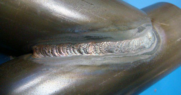
(3) WELD GRAININESS
The grainy appearance of the weld bead is typically caused by welding too hot causing too much base metal dilution.
(1) Find that “sweet spot” that is not too hot and not too cold, and this graininess will go away.
(2) You may have the wrong type of filler metal (4043 instead of 5356).
(3) Always remove all grease, oil, and moisture from the filler and base metal.
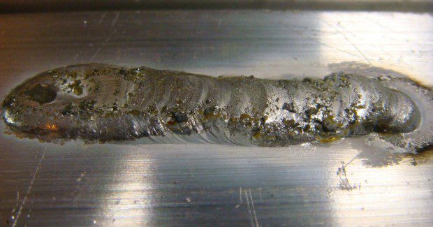
(4) LACK OF FUSION
Lack of fusion at the root of a T-joint or a fillet weld can be caused by a number of factors: improper fit-up, holding the torch too far away from the joint (increasing arc length) and improperly feeding the filler rod, to name a few.
(a) Reducing arc length will provide better directional control and help increase penetration. It is also important not to under-fill the joint or weld too quickly.
(b) Inverter-based power sources offer greater control over arc performance allowing you to tailor the arc to be more focused into the puddle.
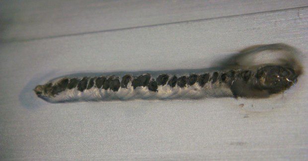
(5) CRATERS
Craters occur at the end of the weld and lead to cracking. Causes include instantly dropping the weld power and removing the filler rod too quickly. Adjust your technique and continue to feed the filler rod while slowly reducing current at the end to fill in the crater. Using a TIG welder with a “crater control” function may also help.
(6) DIRTY BASE AND/OR FILLER METAL
All base and filler metals need to be cleaned, whether it’s mill scale, oxide on aluminum, or dirt and grease. Grind, brush and wipe away all potential contaminants. For cleaning aluminum, dedicate a stainless steel brush to the task to prevent contamination from other metals. Never use brake cleaner!
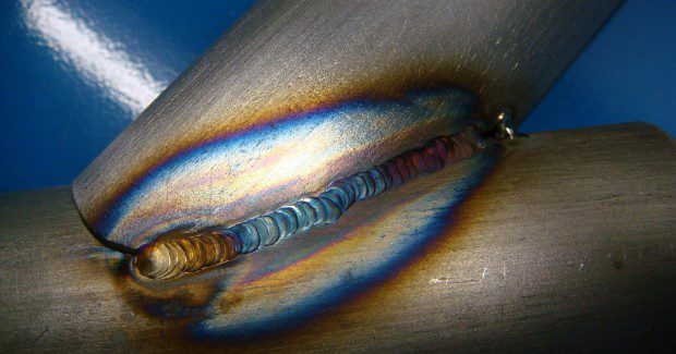
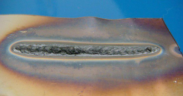
(7) POOR COLOR ON STAINLESS
Discoloration on a stainless steel weld is caused by atmospheric contamination. Each color indicates the temperature of the surface of the weld when the shielding gas dissipated or was removed. Excessive discoloration could be caused by overheating and could degrade its corrosion resistance and mechanical properties, making the weld rejectable; and the only solution would be to scrap the part and start over.
To prevent overheating, reduce amperage, slightly increase travel speed or shorten the arc length. Pulsing also reduces heat input, and it offers excellent control of the weld puddle. “AWS D18.2: 2009 Guide To Weld Discoloration Levels On Inside Of Austenitic Stainless Steel Tube” is an excellent guide to help determine when the level of discoloration may or may not be acceptable; you should always refer to the welding code you are using to be sure.
(8) SUGARING ON STAINLESS
Sugaring (oxidation) occurs around the weld when it is exposed to oxygen in the air. The best way to prevent sugaring is to ensure you have adequate gas coverage on the front and back of the weld and to be sure that you do not overheat the weld.
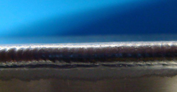
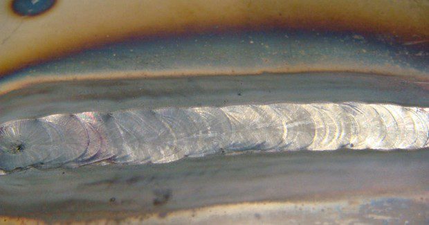
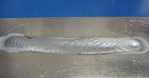
(9) TOO MUCH AMPERAGE ON ALUMINUM
Setting the amperage too high on aluminum creates a wider profile, an ill-defined bead and can potentially lead to burn-through. To solve this problem, reduce amperage and/or increase travel speed.
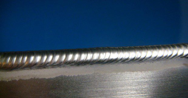
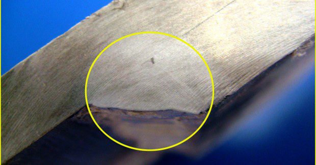
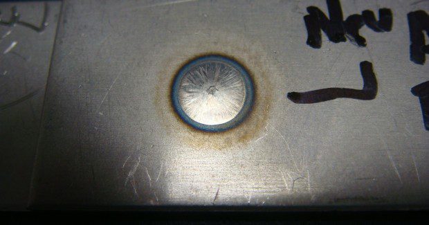
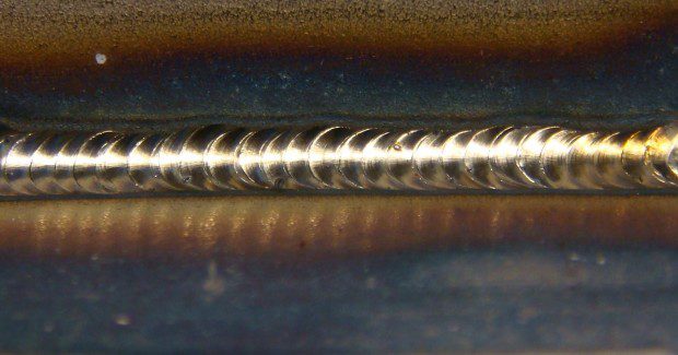
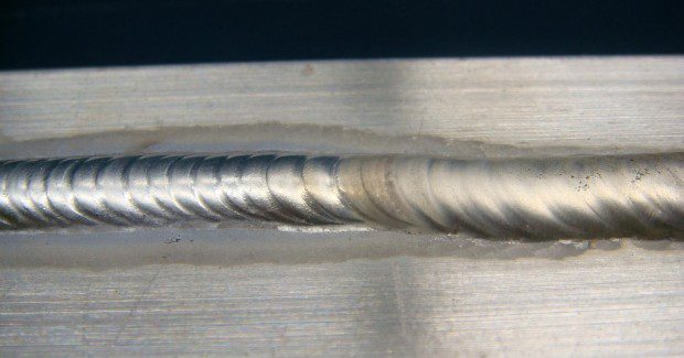
(10) PROPER ARC LENGTH CONTROL
The color change in the middle of this aluminum weld bead can result from an increase in arc length (arc length is directly proportional to voltage). Holding too long of an arc increases overall heat input, increases the potential for distortion, widens the weld bead while decreasing penetration and affects weld bead appearance. Practice holding a consistent arc length to improve heat input control and weld bead quality.
Note: Brad Hemmert, who helped with this analysis, is a welding engineer with Miller Electric Mfg. Co.
Subscribe to learn the latest in manufacturing.
Subscribe to learn the latest in manufacturing.
Industry News