State of the Art: CNC Plasma Cutting Software
Buyer’s Choice: A better understanding of the necessary software required for the newest highly productive CNC plasma machines separates the investment of a hands-on, low volume shop from one with high volume, repeatable parts. Here are the reasons why.
Posted: March 7, 2012

“The buyer’s choice today is to spend a bit less on the system when initially purchased and rely on an expert operator in the shop to ensure the machine cuts consistently, or spend a bit more on components and CAM software that can automate 99 percent of the parameters that promote good cut quality, low operating cost (consumable life, low scrap rates) and high productivity.”


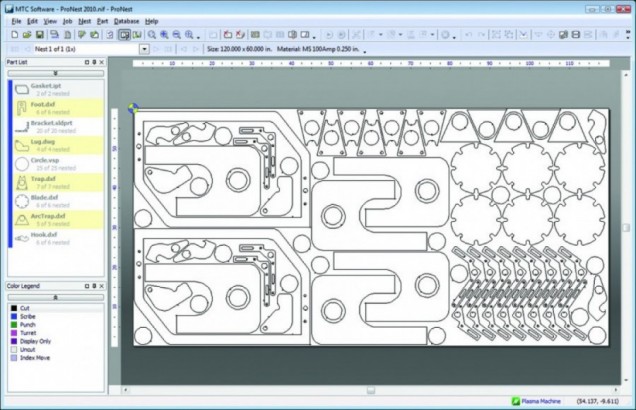
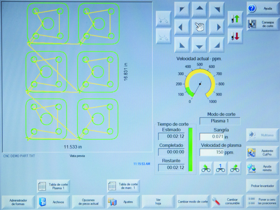
PRIMARY CAD, CAM, CNC SOFTWARE FUNCTIONS
Above we have a simplified explanation of the basic versions of the three types of software on most CNC plasma machines. There are some machines that are usually aimed at the low cost “entry level” segment of the CNC plasma cutting market that actually combine the CAD and CAM software so the operator can do actual CAD drawing on the shop floor at the machine control. This function:
- Eliminates the need for an expert operator.
- Allows the operator to do (time consuming) part drawing at the machine, which is definitely not conducive to high levels of productivity, but is probably necessary in a small, low productivity shop where it makes sense.
Read through the simplified descriptions listed above and you will notice that many plasma systems require a lot of programmer and or operator input. Some of this input (cut speeds, amperage, cut height, etc.) can be read from an operator’s manual and loaded by the operator, while some (kerf width, speed adjustments, lead in style and length, etc.) must come from operator experience.
Systems that use more basic levels of CAM and CNC can be expected to perform better on cut quality and repeatability with a more expert operator. Since CAM software has the ability to (1) read the features on a raw part drawing file, (2) store reams of data, then (3) write the machine code the CNC uses as the roadmap to cut the parts, it makes sense that integrating the data that provides the best cutting performance into the CAM software will allow for better cut quality and repeatable performance without the need for an expert machine operator.
With that in mind, some recent releases from major CAM software developers dramatically improve the CNC plasma cutting process in terms of accuracy, productivity and repeatability of cut quality. These improvements make some of the high end, high definition class cutting operations much more efficient and productive. Even more important, the operator’s job today is more tuned to loading the material, ensuring that the correct consumables are in the plasma torch, and pushing the start button.
Some of the newly advanced functions that the high-end CAM software systems have taken on in regards to CNC plasma cutting include:
- Importing drawing files in many formats (not just .dxf).
- Recognizing features of the part drawing, then applying profiles such as lead ins, lead outs and cut speeds that are proven to work best.
- Applying the correct kerf width from an “expert” database for the material , thickness and power level being cut.
- Nesting parts by using either simple arrays or true shapes to effectively rotate and accurately fit each part for best plate optimization and efficiency (based on selected part quantities).
- Automatically correcting CAD drawings with some errors, close open paths, etc.
- Aligning grain structures of some materials, if needed.
- Automatically starting the plasma on a previously cut edge (easier on consumables, faster piercing) for better consumable life and less top spatter.
- Supporting multiple plasma torch heads.
- Automatically applying start-and-stop points in a manner that eliminates the possibility of colliding with a tipped up previously cut part.
- Applying start-and-stop points that minimize heat input to the plate.
- Automatically setting all plasma, height control, and normal operator set parameters from an expert database so the operator only ensures the correct material is on the table (when used with the correct plasma and height control equipment).
- Generating shop reports with productivity data.
- Generating and calculating costing reports.
- Pre-piercing all start holes – advantageous for thick plate, difficult piercing applications.
- Automatic chain cutting – which links parts with no internal cutouts for less pierces, longer arc on time – which is beneficial to consumable life.
- Tying into MRP/ERP systems to control plate inventory, track and suggest use of plate remnants.
- Automatically cutting up the plate skeleton for easy, quick removal.
- Recognizing hole profiles and adjust parameters and process gases to eliminate taper in plasma cut holes (on steel), when coupled with the compatible plasma and CNV.
SUMMARY
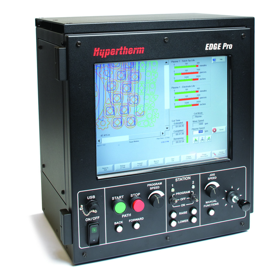
In clarifying the three different types of software that are typically used with industrial CNC plasma machines, the CAD drawing software is (of course) very important and has gotten easier to use over the years. The CNC operating software is in the machine control doing its job interpreting input and sending the right signals to all of the machine components. But it is most clear that the CAM software is now being called upon to take over the expert decisions that were once in the machine operator’s hands.
This means the buyer’s choice today is to spend a bit less on the system when initially purchased and rely on an expert operator in the shop to ensure the machine cuts consistently, or spend a bit more on components and CAM software that can automate 99 percent of the parameters that promote good cut quality, low operating cost (consumable life, low scrap rates) and high productivity.
If you are more of a hands-on low volume shop, perhaps using an expert operator is a viable solution. If you need high volume, repeatable parts and have the need to keep operating costs down, perhaps it is time to take a look at the available CAM software solutions. Many of these major changes have occurred in the last four to five years and will improve your productivity so much that they are worth every extra penny!
Subscribe to learn the latest in manufacturing.

Industry News