Get It Right the First Time, Every Time
CNC machine tool efficiency is all about managing the components that must come together in proper alignment: the machine spindle, toolholder assembly and workspace.
Posted: August 21, 2012


The global market changed manufacturing into a competition that constantly demands shorter lead times, better quality and lower production costs. Individual manufacturing processes are now races to the finish line and, at the end of each race, another one starts. These nonstop races run at ever increasing speeds. As machine tools increase their cutting and rapid rates, safety requirements also increase as these higher speeds require the entire complement of production components to be managed: the accuracy and rigidity of the machine tool spindle, the toolholder assembly, the workholding device and the workpiece are all critical.
Racing every day can push your machine tool maintenance schedule to the limit and leave little time for the pit crew to manage other important aspects of your production cell. Unscheduled production stoppages due to machine and tooling issues will happen during the race. Efficiency and preparation are the only ways to reduce minutes of downtime into seconds when you are trying to keep a machine running for as many hours in the workday as possible.
A lot must happen behind the scenes before an operator can push the cycle start button on that machine. A lot more should also happen while the machine is running, but in a typical shop this does not happen for an assortment of reasons. The most common of these, “it worked the last time,” can only get by for so long before something goes wrong.
Like a driver and pit crew trying to capture first place for producing quality parts with the least amount of costs, these endless races place tremendous pressures on your machines, programmers, setup personnel and operators. In an endless race, your driver and pit crew must be fully resourced.
Delays are never part of a race plan, so how do you empower your production staff? What resources do they need to reduce downtime during and between races? Attention to detail on all fronts will help achieve ultimate production efficiency. The cost to address these details is minimal when compared to the operational losses incurred by a cell that does not run at peak performance. There is no better time than right now to equip your production staff with the resources they need to stay in the race.
A winning formula always includes a well-equipped programming staff. Investing a considerable amount of money in equipment and training for programmers will provide the necessary CAD/CAM resources they need to find the shortest cycle times in the race for production speed. If your programmers have the advantage of CAD/CAM, what edge are you giving your setup and operational staff? After all, they are your front line that is responsible for keeping your machine tool in the race.
MORE TIME ON THE RACE TRACK, LESS TIME IN THE PITS
After a program proves out with CAD/CAM, a good production team can submit and pass a part through first article inspection after only one try. Given additional time and resources, your setup and operational staff should also be able to:
- Achieve a scrap rate of zero
- Optimize tool life
- Maintain machine tool health
The search for opportunities to cut cost must include a review of the causes of all unscheduled machine downtime. Addressing these stoppages will enable you to implement a plan to keep everyone and everything operating continuously at peak performance. The investments are minimal and the extra time required by operational staff to execute these functions will be quickly recovered through less downtime and increased part quality.
All of the metrics involved in preventative maintenance and life cycle management can be used to reduce overall costs and increase reliability. These are absolutely necessary if one wants to meet all production deadlines and achieve the ultimate level in manufacturing: a scrap rate of zero. Managing time consumption during these activities is crucial . . . to increase the responsibilities of your production team, you must first make sure they are well trained and resourced.
Since machine tool performance does not normally degrade over short periods of time, what typically happens is that many small occurrences stack up to create an issue. Identifying the causes of these small occurrences, noting their effects and correcting them as soon as possible is critical to the long term health of your production equipment and also your production staff – because when there are no failures, no one is responsible for failure.
What many consider to be machine tool accessories are actually necessities for companies that aspire to be the best. When you want to get it right the first time and every time after that, it is imperative that you pay proper attention to and manage variables that are not debugged by your CAD/CAM system. Specifically, attention should always be paid to the:
- Machine Spindle
- Toolholder Assembly
- Machine Table Work Space
These unaddressed variables – unsufficiently modeled during tool path verification – can play havoc with form and positional tolerances, feature size and surface finish. Since your CAD/CAM systems will not consider variables in machine spindle or toolholder run-out, cutter performance will always be an issue. The rigidity of the toolholder and workpiece are also critical to producing acceptable quality parts.
MANAGE YOUR MACHINE SPINDLE
It is possible to cost-justify a new machine by projecting downtime and lost productivity due to age, wear and abuse. It is also possible to cost-justify the care of an existing machine. Exercising due diligence in care and maintenance can extend the amount of time before a machine is no longer able to be competitive.
Most companies follow the manufacturer’s guidelines for maintenance, but these instructions do not insure that the machine will continue to perform as if it were new. Instead, an in-depth maintenance and care schedule is your best investment to keep the machine tool in good operational condition and capable of producing quality parts.
This starts with the CNC spindle because its condition directly affects the machine tool’s performance. Everyone around a machine should be encouraged to clean and check its spindle as often as possible. Your spindle management checklist should include inspection of the:
- Retention Knob Pull Force
- Amount of Dynamic Run-out
- Accuracy of Mating Surface
- Cleanliness of Mating Surface
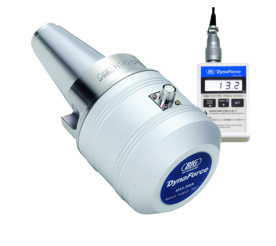
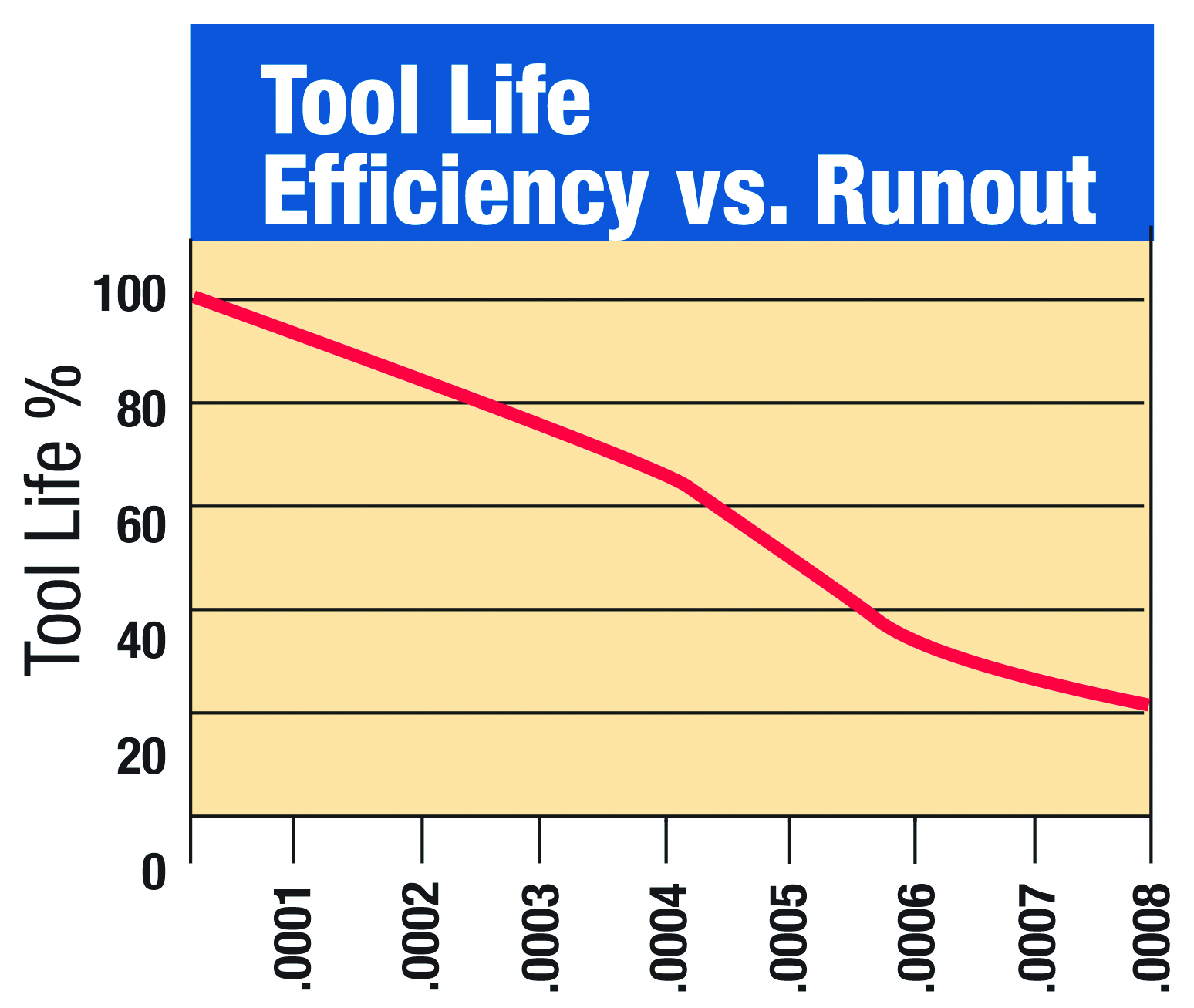
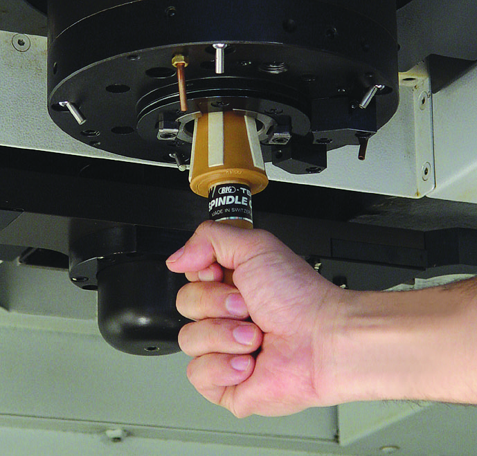
The tools required to perform these functions are readily available. Since spindle rigidity and accuracy directly affect the machine tool as a whole, you should acquire a retention knob pull force gage for your spindles. Test the draw bar force on a regular basis. Should it fall below a certain level, your tool life and surface finish will decrease.
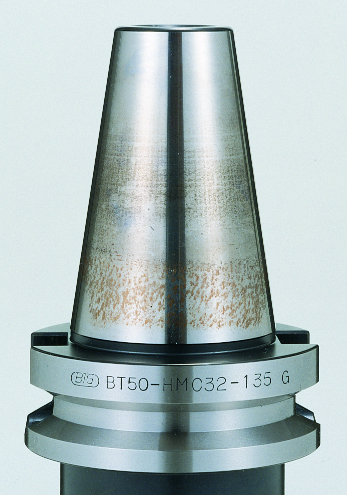
Low draw bar force can also damage your spindle and toolholders. Continual operation of a machine with low draw bar force allows the two mating surfaces of the toolholder and the spindle to rub. This lack of rigidity between the spindle and toolholder may result in friction that degrades the surfaces of the toolholder and spindle, leading to premature failure. This wear condition, which visually manifests itself on toolholders and spindles, is referred to as fretting.
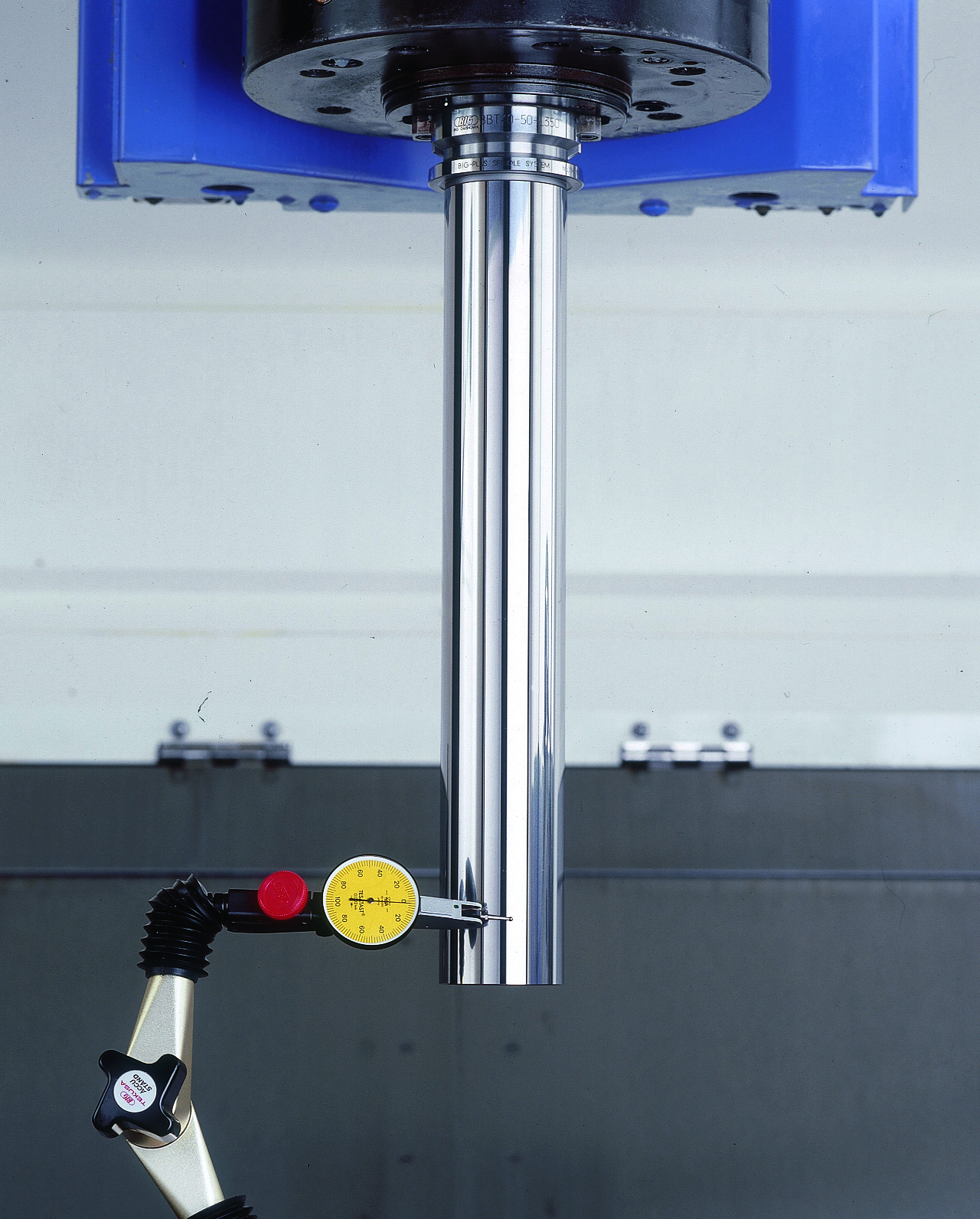
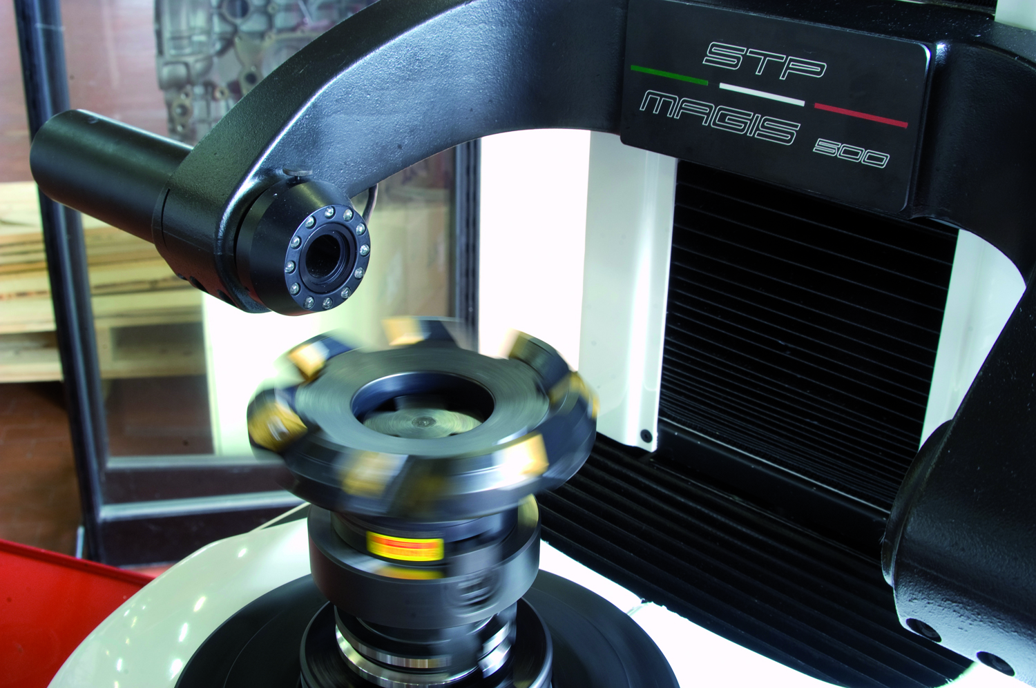
Frequently check the dynamic run-out of your machine spindles using a precision gauge bar, a perfectly concentric steel cylinder that measures the spindle rotation against its centerline. Lower spindle run-outs yield an increase in machine tool performance, extend tool life and, most importantly, extend your spindle life. Visual inspection and gages should be used to check the spindle geometry. Excessive spindle wear can only be corrected by regrinding, so take control of your machine tool spindle.
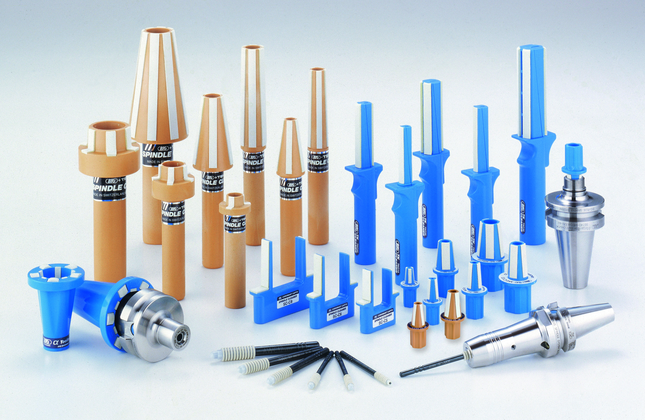
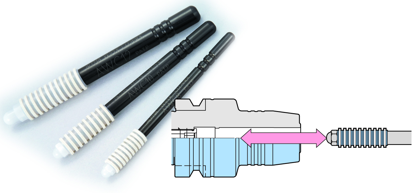
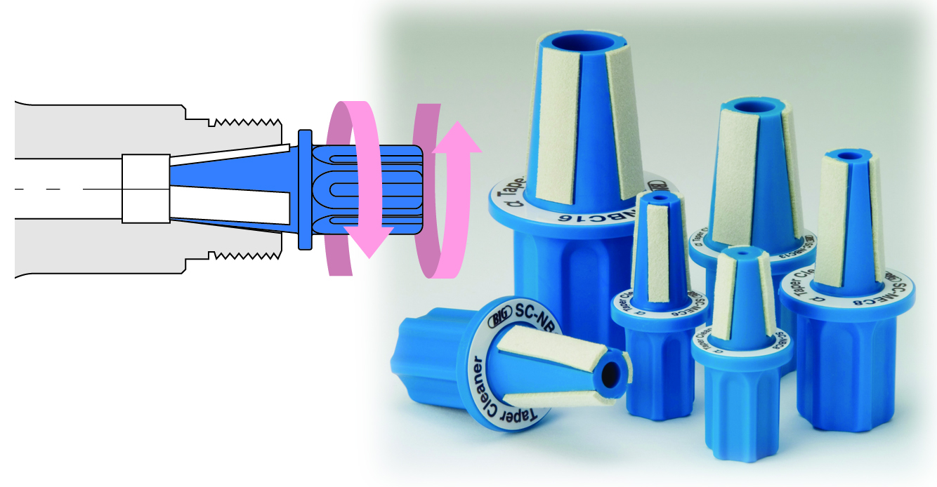
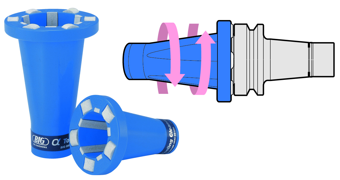
Since machine tool run-out stems from wear of the spindle bearings or the ground spindle geometry, these are important checks. To operate correctly, machine spindles must be kept clean. Any particles or contamination that gathers between the two mating surfaces will cause the surfaces to wear away, weakening the fit and severely impacting machine accuracy. Using spindle cleaners to wipe clean the spindles’ contact surfaces several times a day improves precision and prolongs the life of the machine tool, the cutting tools and toolholders that go into the spindle.
Special toolholders are available the use the coolant feature of the machine spindle to clean the spindle face automatically. All of these procedures can be worked into the day-to-day operations of your machine tool with minimal or no negative impact to your current production capacity.
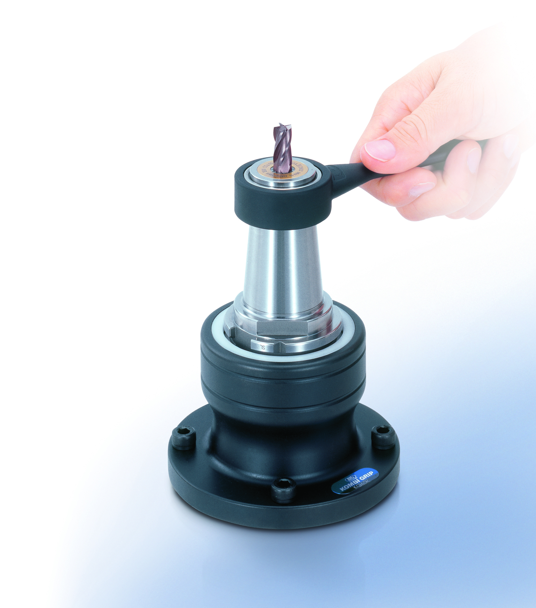
MANAGE YOUR TOOLHOLDER ASSEMBLY
The relationship of the tool to the toolholder is just as important as the relationship of the toolholder to the spindle. Unlike spindles, which operate within the controlled environment of the machine, toolholders can be exposed to many pollutants all around the shop. During storage and between uses, toolholders run a high risk of picking up oils, dust and other particles that can contaminate their surfaces. Cleaning the exterior of your toolholders is an important step before placing them into your tool changer or spindle.
http://youtu.be/Ko_EhSeL6oQ
Before loading a cutting tool into a machine, several factors may need to be qualified. The process of assembling a tool can introduce variables such as:
- Run-out
- Balance
- Size
- Rigidity
In order to control these variables, use clean components that are geometrically correct. The toolholder is designed to hold the tool with sufficient clamping force to overcome the forces of the cutting operation and deliver the tool to the spindle centerline. Both of these functions can be degraded by many forms of contamination. Reductions in gripping strength and deviations from centerline lowers tool performance, so cleanliness is critical to achieving maximum tool life and material removal rates.
All toolholders have a better chance of delivering the tool to the proper location and holding them firmly when components are clean and free of contamination. Complex toolholders such as collet chucks should be completely disassembled and cleaned between uses. Wipers are available to clean the internal surfaces of the collet body. The spring collet should have contamination removed with cleaning systems such as ultrasonic or high-pressure washers.
Once all components are cleaned, toolholder assembly can begin. The toolholder should be protected while it is being assembled and disassembled to keep from damaging surfaces. Tool assembly devices are available to assist in safely gripping toolholders. Avoid serrated grippers or loose fits which can easily scar tools and toolholder shanks. When tools and holders are required to rotate at high speeds, it is critical that their original surfaces are preserved.
When spindle speeds require a balanced tool, there are two approaches to delivering a qualified tool to the spindle. The first approach uses precision, balanced components. If everything is clean and in proper operating condition, components can be assembled and sent directly to the machine tool. If the toolholder components and cutting tool are manufactured to a lower level of precision, they can be assembled, balanced offline and then be transferred to the machine tool.
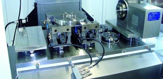
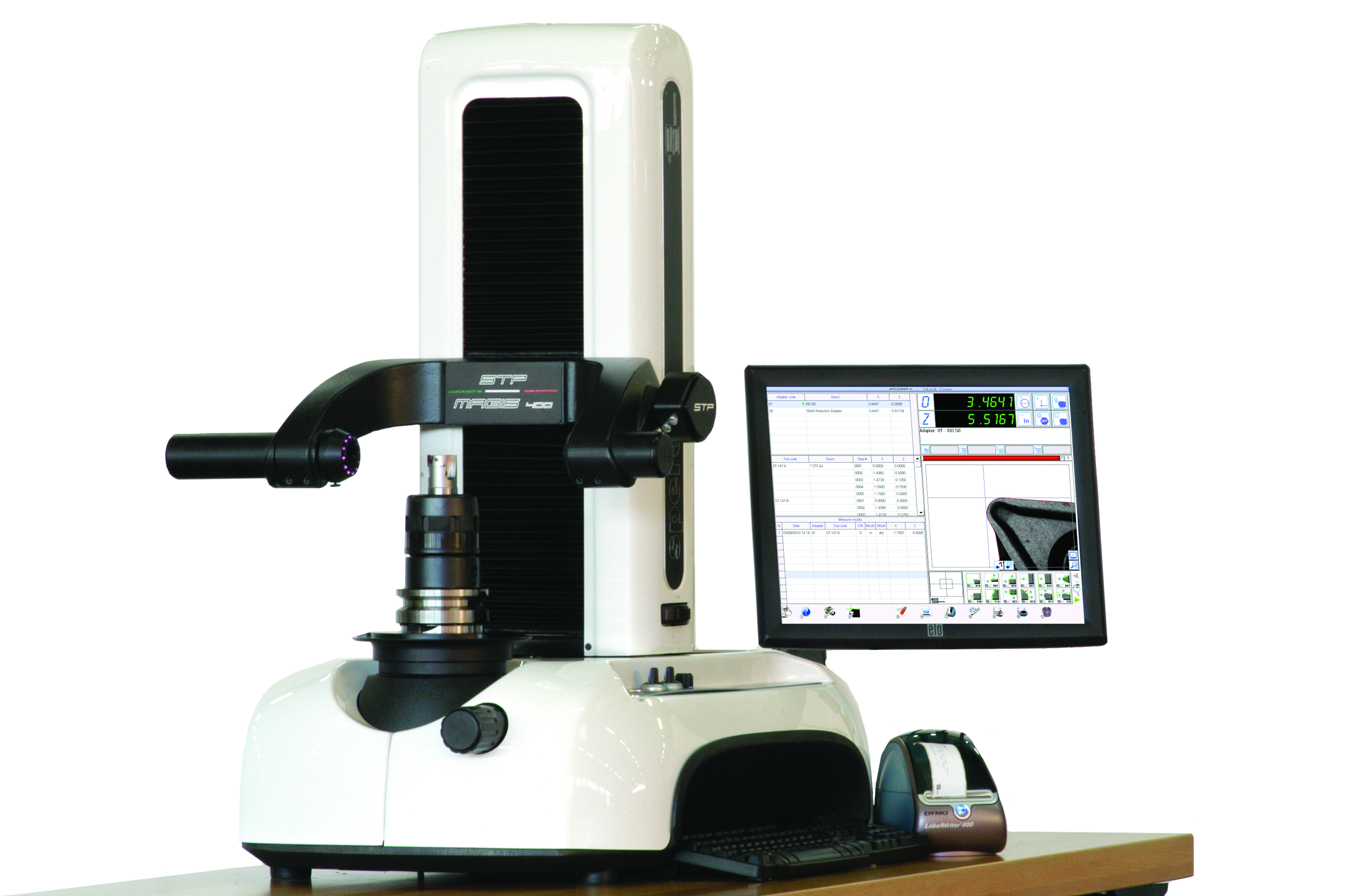
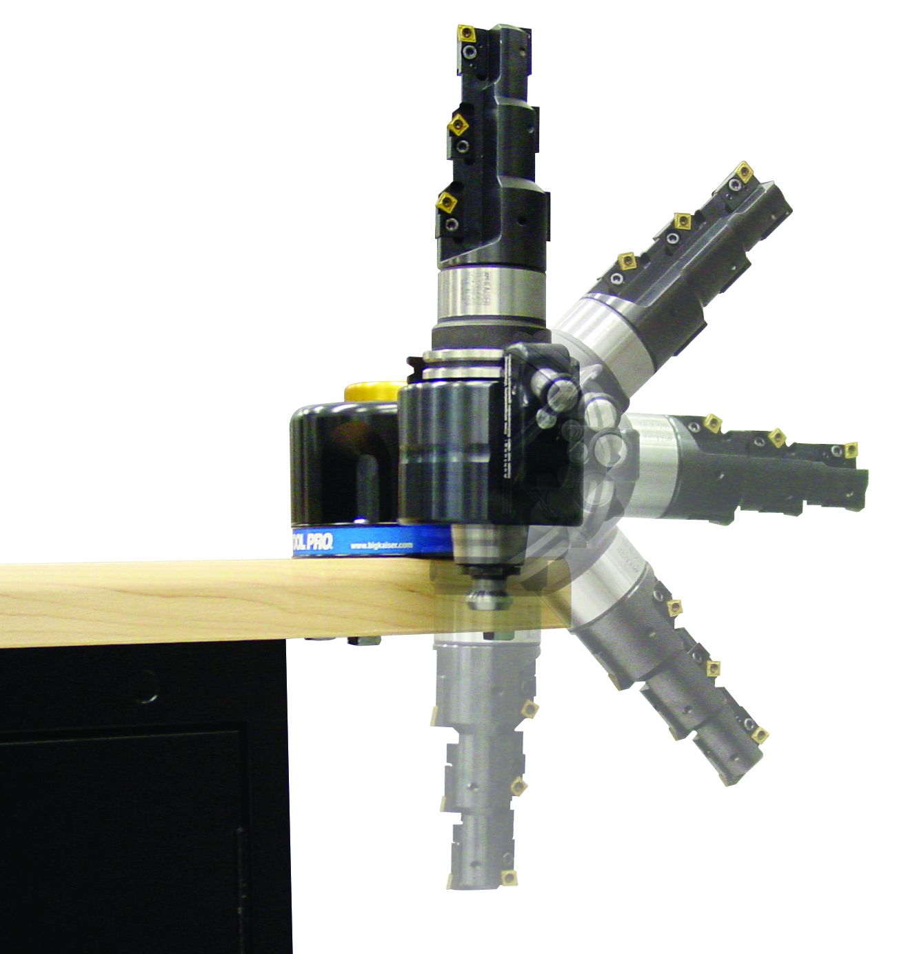
Offline tool presetters are excellent ways to find and remove run-out from tool assemblies outside of the machine spindle. They are also the best way to set tools to specific sizes. As a measuring and inspection device, tool presetters can inspect and measure all forms of geometry associated with the most complex cutting tools. In lieu of offline presetting, probing systems can be installed in the machines to measure and monitor tool lengths.
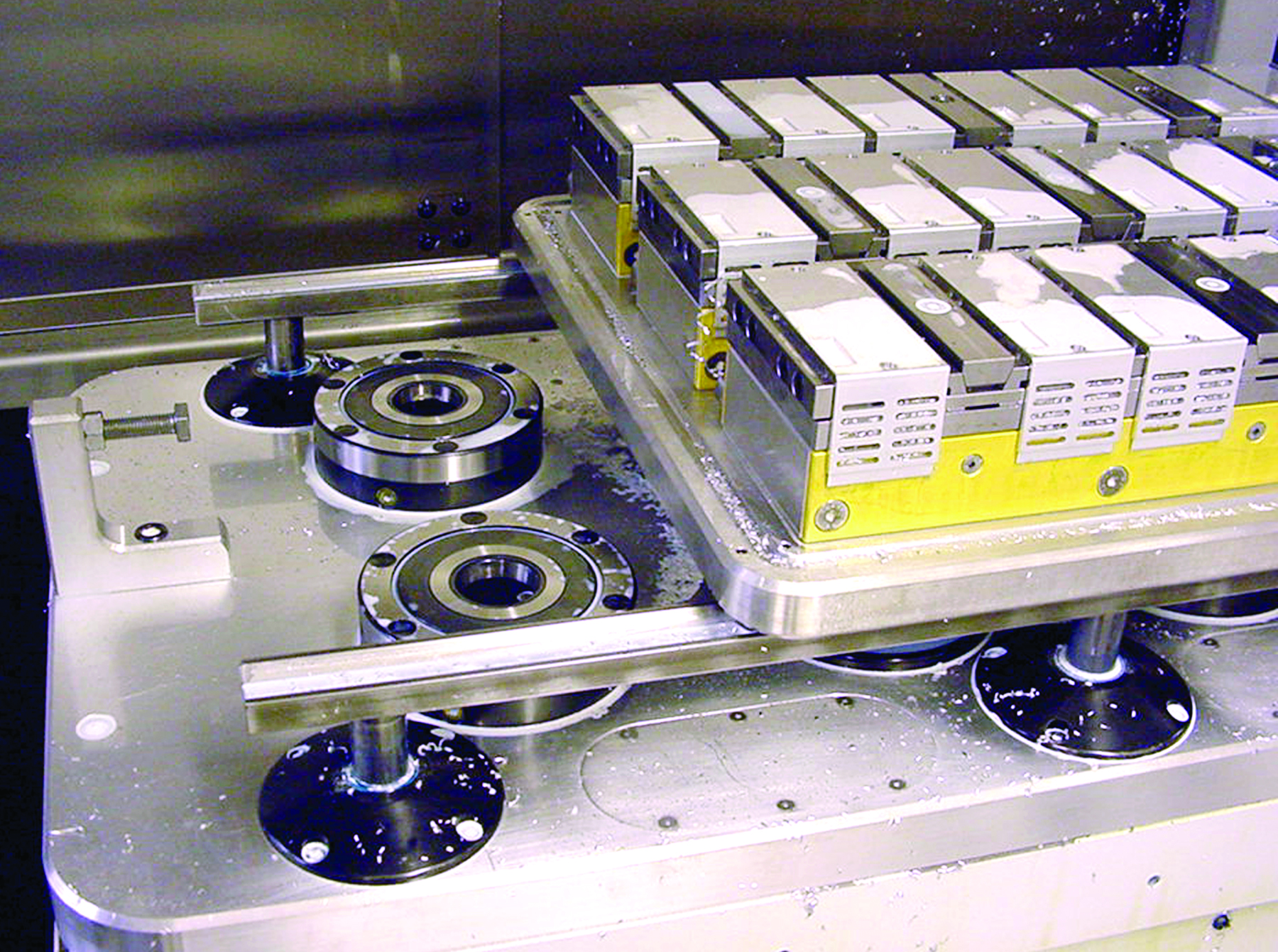
MANAGE YOUR MACHINE WORKSPACE
Workpiece handling must be treated the same as toolholder assemblies. If you need a large number of tools available on-demand to meet your production needs, expand your tool changer or quickly swap out toolholder assemblies in the carousel. Consequentially, if you need a large number of workholding devices to produce all of your products, swap out workholding devices or add machine tables.
Duplicating machine tables requires large amounts of floor space and is usually cost prohibitive. Pallet pools on horizontal machining centers have proven to be the exception to this rule. If you cannot duplicate machine tables, then have the workpiece handling system positioned and clamped in a way that allows the production process to commence without having to indicate in the handling device. Most companies choose to retrofit a quick change positioning and clamping system to their machine table to facilitate these changeovers.
These workholding systems must provide fast, accurate and rigid positioning and clamping. The most common quick changing machine table setups systems are:
- Grid plates
- Zero-point clamping systems
- Shuttle tables (for vertical machining centers)
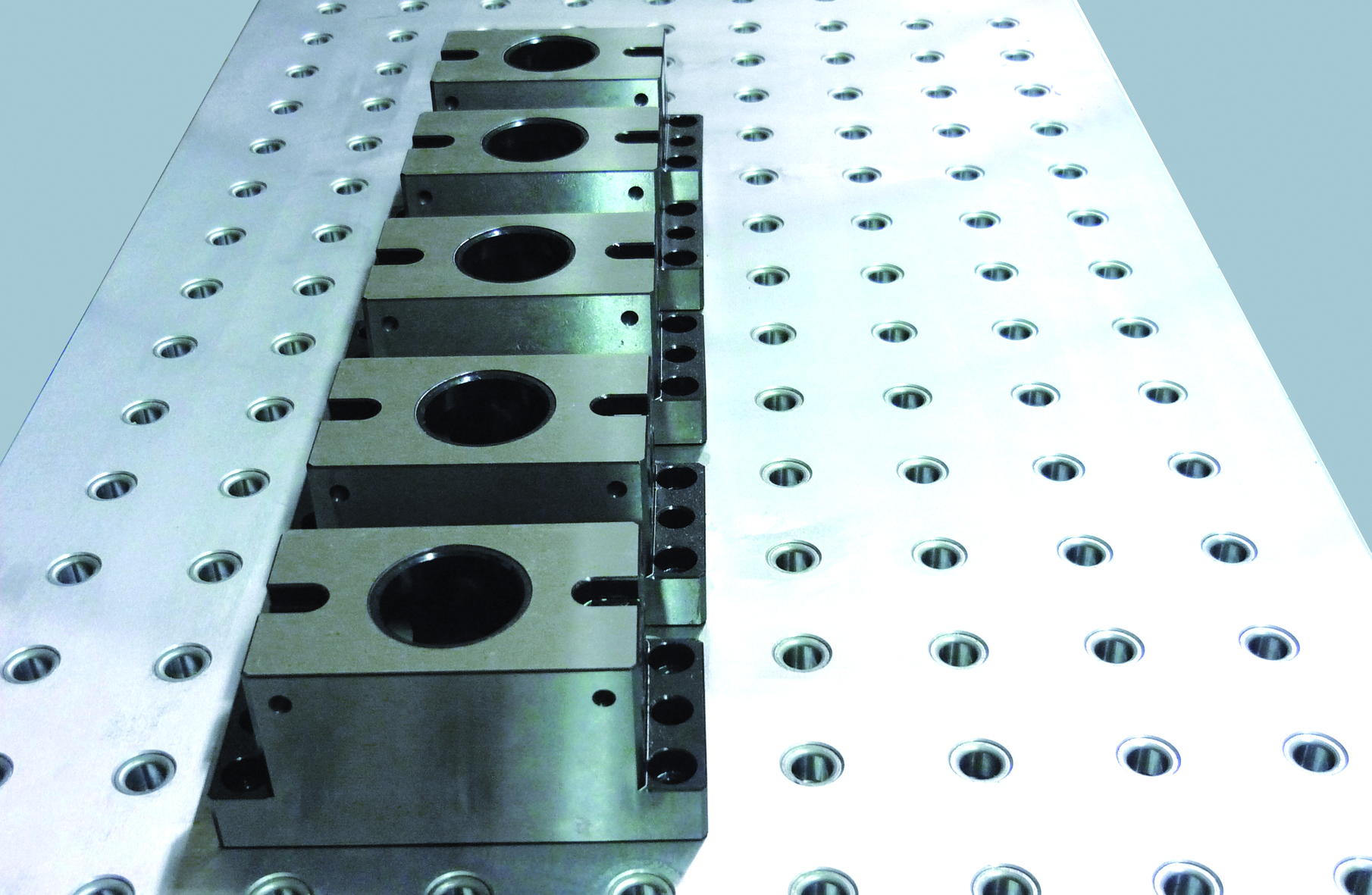
Grid plates provide a repetitive series of accurate bushing locations that accept positioning pins to locate workholding device or workpieces. These positioning locations intermix with threaded locations that provide a means of attaching clamps to hold the workpiece or workholding device with sufficient rigidity for the production process.
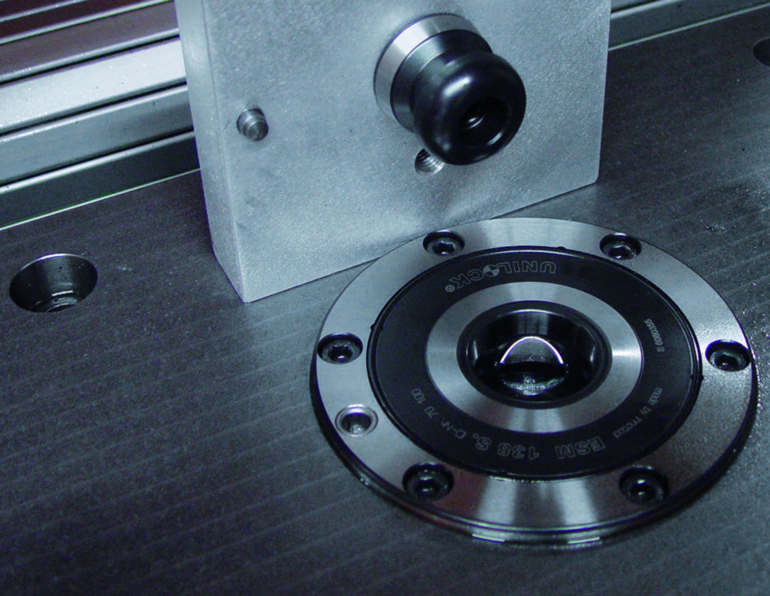
Zero-point clamping systems combine positioning and clamping into a single process. A retention knob with a geometric reference datum is appended to the workholding device or workpiece. The clamping process draws the retention knob into a ground reference to allow simultaneous positioning and clamping. Small workspaces can be addressed with a single retention location; larger components with multiple clamping locations.
Shuttle tables consist of a track mechanism that connects the machine table thru a rail system to a table storage position. One workholding table can be shuttled out of the machine while a second table is shuttled into the machine.
Are you in the race or temporally stalled in the pits?
CNC machine tool efficiency is all about managing the components that must come together in proper alignment. Your operational staff can already manage the machine spindle, toolholder assembly and workspace. Your programmers can link all of the pieces together. All you need to do is provide the resources and turn over the responsibilities to them to deliver production uptime and quality.
Subscribe to learn the latest in manufacturing.

Industry News