Design Considerations for Robotic Welding Cell Safety
Inherent differences in robotic welding cells make it important to develop a safety strategy for each cell and select the optimal technologies to match that strategy.
Posted: May 24, 2013
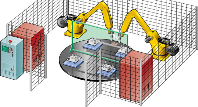
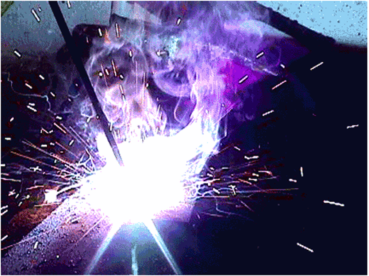
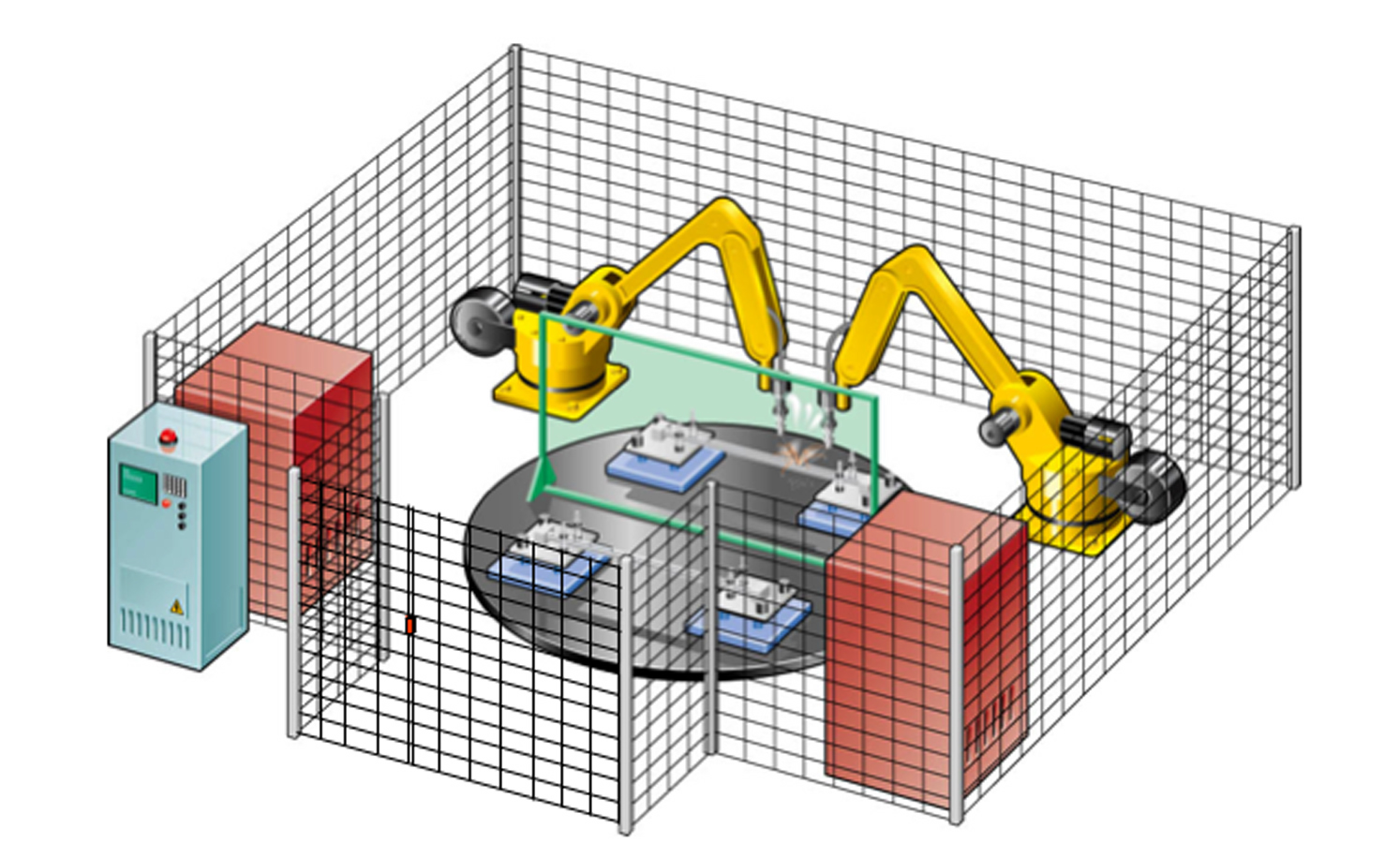
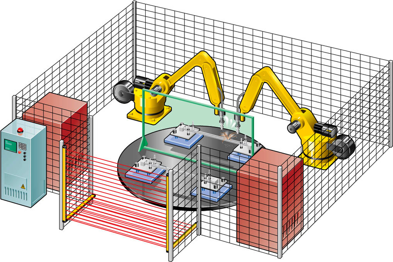
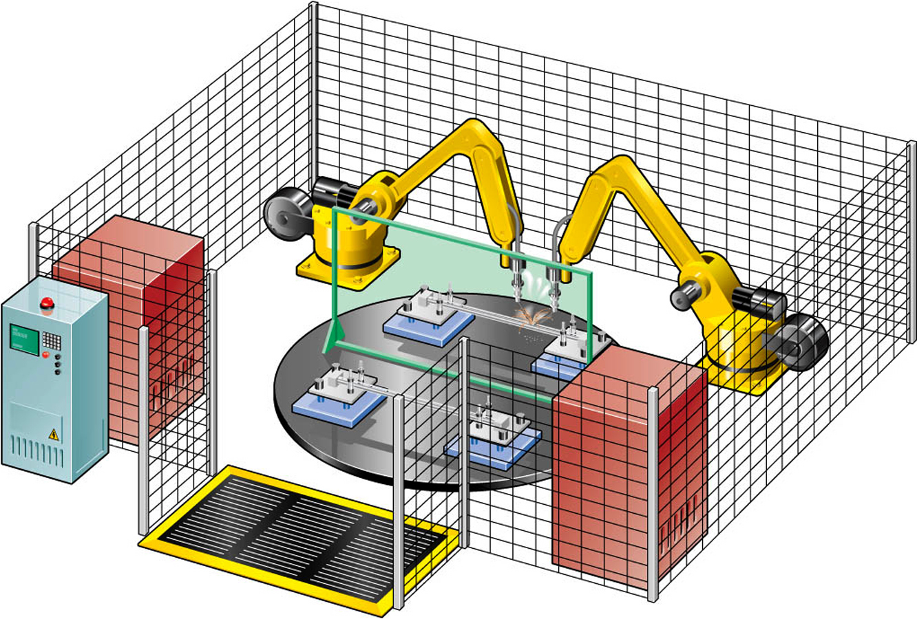
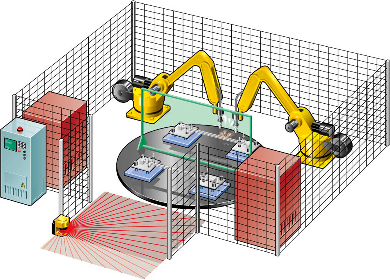
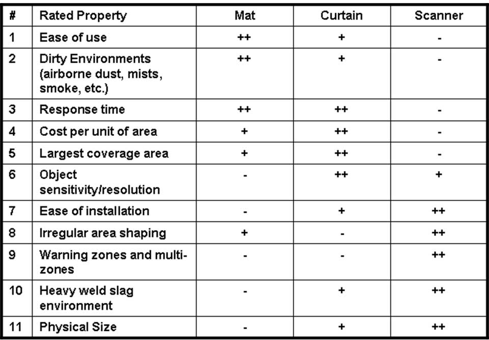
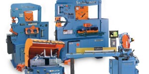
Figure 1. A typical robotic welding cell.
(Click on illustration to enlarge it)
Figure 2. Light flashes are a potential hazard.
(Click on photo to enlarge it)
Figure 3. An interlocked gate.
(Click on illustration to enlarge it)
Figure 4. Horizontal and vertical mount light curtains.
(Click on illustration to enlarge it)
Figure 5. Safety mats.
(Click on illustration to enlarge it)
Figure 6. A laser scanner with warning and safety zone.
(Click on illustration to enlarge it)
Figure 7. A comparison of safeguard technologies.
(Click on table to enlarge it)


Robotic welding cells deliver remarkably high levels of quality and productivity at a substantially lower total cost of ownership than just a few years ago. Yet today’s robots cannot function without human interaction so robots, people and other machines need to be protected from one another. A safety strategy should be developed for every robotic welding cell – this involves risk assessment and risk reduction. The usual approach is to provide fences around the cell and an entry way that enables operators to enter to load and unload parts but keeps people out of harm’s way when the cell is operating. Primary alternatives for safeguarding the cell include physical barriers, light curtains, safety mats and laser scanners. This article will consider robotic welding cell safety in detail and consider the advantages and disadvantages of various risk reduction measures.
The increasing popularity of robotic welding cells can be traced to a number of factors. The amount of time and level of skill required to program robots has been substantially reduced, and the flexibility of the latest generation of robots makes it possible for them to go from part to part very quickly as long as the work holding tooling is designed to be quickly changed. The level of skill and experience required to operate a robotic welding cell is usually less than that which is required to produce high quality manual welds. The dollar cost of robotic welding cells has dropped substantially over the past decade, due largely to cost reductions in the electronic equipment that makes up a high proportion of their value. Over the same period, the speed, accuracy and other capabilities of robots designed for welding applications has steadily increased.
ROBOTIC WORK CELL SAFETY CONCERNS
However, robotic welding cells present significant safety concerns. Robots lack the intelligence of a human operator, and in the event of a programming error or hardware malfunction they have the potential to unexpectedly move large distances at a high rate of speed. The welding operation itself generates intense light flashes, smoke and fumes, and high electric currents. Protecting employees against these hazards is required to comply with regulations and, to protect a company’s most valuable assets, its employees. The same equipment that prevents injuries also provides an opportunity to make a positive impact on the bottom line. This is because the cost of a work-related injury goes far beyond hospital and medical costs.
Additional costs that commonly result from an accident include rehabilitating and retaining the injured worker, time spent by supervision and management on the incident, machine downtime, and possible litigation*. According to a poll conducted by the Liberty Mutual Group, 61 percent of executives claim for every dollar spent on investments in workplace safety three dollars are saved. OSHA’s Office of Regulatory Affairs provides similar, although even more encouraging results, suggesting four to six dollars saved for every dollar invested. Furthermore, 95 percent of executives in Liberty Mutual’s poll believe workplace safety has a positive impact on a company’s financial performance.
The poll by Liberty Mutual also revealed that 40 percent of the executives reported that one dollar spent on direct accident costs generates from three to five dollars of indirect costs. So consider that an accident with direct medical and compensation payments of $15,000 will likely cost between $45,000 and $75,000 more in indirect cost. Now consider this: Indirect costs account for the majority of the accident expenses and are typically not covered by insurance.
The primary regulations on robotic safety are the Robotic Industries Association ANSI/RIA 15.06-1999 (R2009) American National Standard for Industrial Robots and Robot Systems – Safety Standards, and the RIA Technical Report RIA TR R15.106-2006. The purpose of these documents is to provide guidelines for industrial robot manufacture, remanufacture and rebuild; robot system installation; and methods of safeguarding to enhance the safety of personnel associated with the use of industrial robots. Minimum performance standards are specified for safety circuit integrity including electronic, pneumatic, hydraulic, electrical and mechanical components. For example, the new standard requires two separate stopping circuit functions for the robot, one for safety stops initiated by safeguarding devices and the other for emergency stops.
It is important to note, however, that this standard has been recently revised. ANSI/RIA R15.06-2012 was approved and adopted in early April 2013. The 2012 revision is a national adoption of ISO 10218-1 & -2, which only address the manufacture and integration of a robot. The RIA committee is working on new Technical Reports, (R15.306 & R15.406) to address risk assessment and safeguarding which are not included in the new standards.
DEVELOPING A SAFETY STRATEGY
The standard directs that companies that use robots develop a safety strategy beginning with identifying the machine limits and functions that pose a potential hazard. The degree of risk due to the hazard is then estimated in order to provide a basis for judgment at later stages. The risk assessment should consider the severity of potential injury, frequency of exposure and probability of injury. A risk evaluation is then performed to determine whether additional safety measures are needed to reduce the risk.
Risk reduction is then performed and safety measures are selected based on the information derived from the risk assessment process. After the implementation of these measures the risk assessment is repeated to determine whether the proper degree of safety has in fact been achieved. Nearly every risk assessment will point to the potential for risk of injury when an operator is within the operating range of the robot during welding operations. Other possible hazards might include the potential for objects to be thrown from the cell and for light flashes from the welding operation.
On the other hand, access is nearly always required to the robotic welding cell for functions such as loading and unloading workpieces and maintaining the welding equipment, robot and other machinery in the cell. So a tradeoff is required. Protection is generally considered to be essential; however ease of entry is often traded off against cost. The best protection is the device or system that offers the maximum safety with the minimum impact on machine operations at a minimum cost. A key factor to consider is how often entry is required. If the welding operation operates at a high rate of production, then operators may frequently need to enter the cell to load and unload parts.
On the other hand, low production rate cells will usually require less frequent entry. The access area requires an entry method that will allow employees to enter the cell when it is safe to do so and keep people out when the cell is operating. Fixed hard guards or fences are typically used to protect the majority of the robotic welding cell. When properly designed hard guards provide the maximum amount of protection, not only keeping people out but also protecting people outside the perimeter from flashes and flying objects. Of course, hard guards cannot normally be used for the entire perimeter because this would make it very difficult to access the robotic cell. Typically, a gap in the hard guarding is defined as an entry to the cell and a more flexible guarding solution is provided here to enable personnel to safely enter the cell.
ALTERNATIVE SAFEGUARD TECHNOLOGIES
One approach to provide access is the use of movable guards with switches interlocked with the power supply in a manner that turns the power off whenever the guard door is open. The control of the robot and other dangerous machine power is routed through the safety contacts of the interlock switch. When guard door movement is detected, the interlock switch sends a stop signal to the guarded robot.
Some interlock switches also incorporate a device that locks the guard door closed and will not release it until the robot is in a safe state. When the interlocked guard is opened its movement should be connected in the positive mode to the safety related contacts of the switch. This ensures the contacts are physically pulled apart or “force disconnected” by the movement of the guard. This is superior to the alternative approach of relying upon spring pressure to open the contacts because spring pressure may not be able to overcome sticking or welding contacts and because the spring may break. Positive mode operation gives forced disconnection of the contacts.
Light curtains are often used in conjunction with hard guards to protect people when the robot and other machinery are operating, while enabling easy access at other times. Light curtains control access to the robotic work cell by emitting harmless infrared light beams across the entrance. When any of the beams are blocked, the light curtain control circuit sends a stop signal to the guarded machine. Light curtains are very versatile and can guard areas many meters wide – sometimes as large as 20 m. Light curtains can be mounted in either a horizontal or vertical plane. When mounted in a vertical orientation, the first beam should begin no more than 12 in above the ground in order to prevent anyone from crawling under it. When mounted horizontally, however, the height of the plane should be based upon the resolution of the sensing field.
Pressure sensitive safety mats provide another alternative for guarding the entrance to the weld cell, and in certain application they can also be installed to protect the inside of the cell. A matrix of interconnected mats is laid around the entry area and an operator’s footstep will cause the mat control unit to send a stop signal to the robot. Pressure sensitive mats can be used both in the entry and inside the safe area. Trim is used to hold the mat in place, protect wiring and provide a smooth ramped surface to prevent tripping over the mat. Caution should be used when selecting safety mats for use in heavy welding environments due to possible damage from sparks and heavy weld slag.
A safety laser scanner is one of the newest technologies to be used for safeguarding robotic welding cells. The laser scanner can be configured to precisely specify the area which should be avoided. The hazardous area is defined as a safety zone, with a typical maximum safety area defined by a 4 m radius. A warning zone with a radius as large as 15 m can be also defined to detect objects that are approaching the safety zone and can be used to initiate a warning signal before the safety zone is actually encroached. More than one guarded area can be configured.
Internal components of the scanner continuously rotate and emit an optical signal to detect the intrusion of objects within an area. The small optical sensor uses pulsed laser light to scan its surroundings. The scanner emits a light pulse and the light hits the first object in its path and is reflected back. The scanner then compares the distance of the object against the known size of its safety zone. If the scanner detects an intrusion into the pre-defined zone, it sends a stop signal to the guarded machine.
TECHNOLOGY COMPARISION
Now let’s compare and contrast these technologies and provide general rules for applying them to different robotic welding cell applications. The interlocked door stands apart from technologies discussed here in that it provides an actual physical barrier. A physical barrier may be required in certain applications such as where a serious risk exists of a robot hurling an object through the cell entryway.
On the other hand, the interlocked door has the disadvantage that the door must be physically opened each time an operator enters the cell and if the production rate of the cell is high the need for frequent opening and closing of the door may have a substantial impact on the productivity of the cell. Safety light curtains, safety mats, and safety laser scanners are all trip devices because they do not restrict access but only sense it. Working without physical barriers, they allow free access for loading and unloading parts, and cleaning. Trip devices will generally enable operators to service the machine faster but will not provide protection against objects that might accidentally come out of the cell nor will they protect against hazards such as weld flash.
In cases where these risks are considered to be significant, they can often be substantially reduced by strategic positioning of the entry. The greatest concern with interlock switches is the potential for an undetected failure that could leave the machine unguarded. This is because all mechanical devices are subject to failures and interlock switches are generally checked only when the switch is cycled, such as during scheduled maintenance.
Light curtains, on the other hand, have no moving parts and continuously perform self-diagnostic routines that ensure that they are operating properly. If their safety functionality should ever stop operating, they will fail safely and sending a stop signal to the guarded machine. Laser scanners also provide diagnostics that will immediately sense a failure and issue a warning while send a stop signal to the guarded cell. A key difference between light curtains and laser scanners is that light curtains can detect an object as small as a finger moving into the hazard zone. Light curtains also provide faster response time than laser scanners so they can be mounted closer to the machine hazard, which saves floor space. Safety laser scanners are normally designed to detect lower extremities such as feet and legs, though newer scanners have adjustable minimum object sensitivity for use in hand and finger detection applications.
MINIMUM SAFE DISTANCE
Because an operator can walk or reach directly into the cell, it is important that the time required to stop the cell is less than the time for the operator to trip the safeguard and reach a dangerous spot. Accurate determination of the safe mounting distance is important in maintaining safety and productivity. The goal is to keep the light curtain as close as possible to the hazard in order to avoid interfering with the operator’s normal motion and conserve floor space while at the same time ensuring that the robot will stop before the operator’s hand or other body part can reach a hazardous point. The American National Standard Institute provides the following formula for calculating the minimum safe distance:
Ds = K (Ts + Tc + Tr + Tspm) + Dpf
- Ds is the minimum safe distance.
- K is the maximum speed at which an individual can approach the hazard in inches per second. A common value for K is 63 inches per second.
- Ts is the total time in seconds for the hazardous motion to stop or for the hazardous portion of the cycle to be completed.
- Tc is the response time in seconds for the machine control circuit to activate the machine’s brake.
- Tr is the response time in seconds of the safety system.
- Tspm is the additional time in seconds allowed by the stopping performance monitor before it detects stop time deterioration. The stopping performance monitor will halt the machine when the stop time exceeds the set limit. If the machine does not have a stopping performance monitor then a percentage increase factor should be added to the measured stop time (Ts + Tc) to allow for brake system wear. A typical value is 20 percent.
- Dpf is the depth penetration factor.
CONCLUSION
This article has provided an overview of the major considerations involved in robotic work cell safety. There is no one best way to protect personnel from being injured in operating a robotic welding cell. Inherent differences in robotic welding cells make it important to develop a safety strategy for each cell and select the optimal technologies to match that strategy.
This article was originally published by Welding Journal Magazine. ©American Welding Society.
Subscribe to learn the latest in manufacturing.
Subscribe to learn the latest in manufacturing.
Industry News