Selecting the Proper Size Welding Cables
Here is the best way to use reference charts for ordering the correct sizes of welding cable for the shop, along with some basic guidelines to follow.
Posted: September 20, 2013


Q: I need to order some welding cable for our shop, but I am not sure the correct size to get. I have seen some reference charts, but I would like an explanation on how to use them.
A: Welding cable is the electrical conductor for the welding current. It consists of a series of fine copper strands wrapped inside a non-conductive, durable jacket (typically some type of synthetic or natural rubber of various colors). The fine copper strands give welding cable more flexibility than other types of electrical conductors, and the insulating jacket is designed to hold up to repeated movement over rough surfaces.
As the current level increases (measured in amperage or amps), the diameter of the welding cable, and resulting cross sectional area of the copper stranding, needs to increase. The concept is similar to the flow of water through a hose. A larger diameter hose is needed in order to carry a greater volume of water. You use a smaller hose to water your garden, while the fire department uses a much larger hose to fight fires.
Welding cable “ampacity”, also known as current capacity or amperage rating, refers to the maximum amount of electrical current that a cable can safely conduct. Besides the cross sectional area, other factors that impact the ampacity of welding cable are its length, ohm rating (i.e., resistance rating), temperature ratings of the insulation material and the ambient temperature. Shorter cables can carry more current than longer cables of the same diameter.
Welding cable is often rated with a conductor temperature of 75 deg C (167 deg F), 90 deg C (194 deg F) or 105 deg C (221 deg F). While the copper wire itself can handle the high temperatures generated by higher amperages before sustaining damage, the insulation protecting them would melt. Welding cables are also often rated for an ambient temperature of 30 deg C (86 deg F).
Higher ambient temperatures can reduce a cable’s ability to dissipate heat into the surrounding environment, and thus reduce its ampacity. In addition, several cables packed tightly together also can have a reduction in their ability to dissipate heat. Multiple cables should be slightly spread apart. Note that while copper is an excellent conductor of electricity, it still has a degree of resistance to the flow of electrons through it. Therefore, some amount of resistance heating will occur in the cable. It is normal for a properly sized welding cable to feel warm to the touch after prolonged welding.
However, if the diameter of cable is too small for the level of current flowing through it, then the cable will overheat. This can result in a potential fire hazard, as well as damage to the cable itself (and ultimately to cable breakage and failure). A breakdown of the insulation jacket also can be an electrical shock hazard.
Conversely, cable that is oversized for a given amperage level does not conduct current any more effectively than properly sized cable. However, larger diameter cable typically costs more per foot or per meter than smaller diameter cable, because of the increased amount of copper strands. Therefore, oversized cables may not be cost effective.
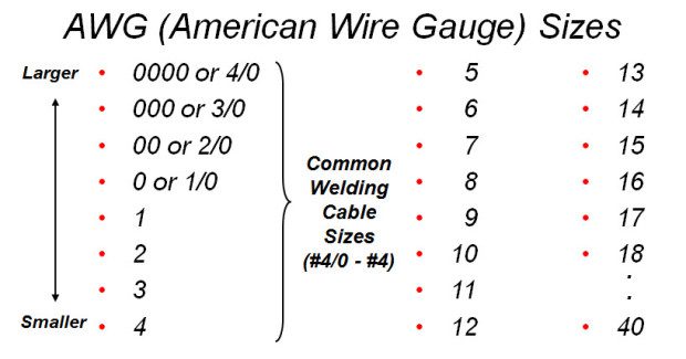
Electrical cable is typically categorized by an AWG (American Wire Gauge) size, where the smaller diameter cable has a larger number. Figure 1 lists the AWG sizes. Gauge (or gage) sizes larger than one are zero, also expressed as 1/0 (pronounced “one aught”), two zeros, expressed as 2/0 (pronounced “two aught”), 3/0 and 4/0. Cable sizes between #4 and #4/0 are typically used for welding cable.
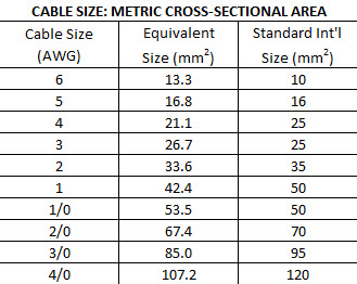
In the metric system, welding cable size is typically expressed in square millimeters (mm2), representing the cross-sectional area of the cable. Figure 2 shows a comparison between welding cables in AWG sizes and metric sizes.
When selecting the proper cable size for your welding equipment, it is best to choose cable that can handle the maximum output of the welder. To do this, you need to determine three factors. These include:
• Total length of the welding circuit
• Rated output of welding power source
• Duty cycle of the welding power source
The welding circuit is the total path in which the electricity travels. It includes the power source, electrode cable, electrode holder (or TIG torch or wire feeder and gun), electrical arc, work cable and work clamp. Figure 3 illustrates the welding circuit. For determining proper welding cable size, you need to add together the full lengths of the electrode cable and the work cable.
The electrode cable attaches to either an electrode holder, TIG torch or wire feeder. The work cable attaches to a work clamp. Note these last two items are often incorrectly referred to as the “ground cable” and “ground clamp”. However, this is improper terminology, as the “ground” lead only applies to the primary side of the welding circuit (i.e., the incoming power cable).
Note that welding polarity does not affect the size of cable needed. It does not matter in which direction the current flows through the welding circuit, whether it be direct current positive (DC+), direct current negative (DC-) or alternating current (AC). Polarity and direction of current flow only affects welding characteristics and electrode selection.
Rated output of the power source is simply the maximum current or amperage level in which the machine is intended to be used (note that some power sources can produce higher currents than their rated output for short periods of time). This rated output level is typically incorporated into the machine’s name. Examples include the “Idealarc® 250” (rated 250A output), Power Wave® S350 (350A rated output), Flextec™ 650 (650A rated output), etc.
Duty cycle is a capacity rating of a welding power source, expressed as a percent (%). It is the percentage of a 10-minute period that the power source can operate at a given output current level before exceeding its thermal limit (i.e., the windings get too hot) and shutting down if it has thermal overload protection. Generally as output levels decrease, duty cycle increases (until 100 percent or continuous output).
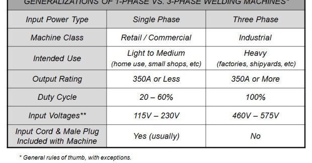
Conversely, as output levels increase (until maximum output capacity), duty cycle decreases. The duty-cycle rating(s) can be found on the power source’s nameplate and/or in the operating manual. The duty-cycle rating of a welding power source is typically related to the welding processes in which it will be used, its intended use and whether it operates off of single phase or three phase power. Figure 4 lists some typical differences between single and three phase power supplies, including their typical duty cycles.
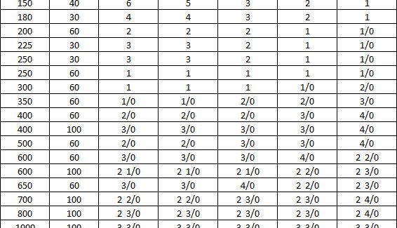
Figure 5 is an example of a chart for selecting the proper welding cable size. Other charts are available from cable manufacturers and welding reference books. As an example, let’s assume you have a 400-amp power source at 60 percent duty cycle and need a total combined length of electrode plus work cables of 100 feet. From the chart, the proper cable size to select would be #2/0 cable. Cable sizes are increased for longer lengths primarily for the purpose of minimizing cable drop. For higher current levels, two or more cables are often recommended and should be hooked up in parallel or together in order to share the current load.
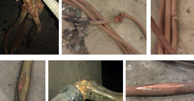
It should also be noted that, in addition to proper cable size selection, it is very important to maintain the welding cable and the cable connections in good condition. Any cracks, cuts, worn spots, etc., in the weld cable can decrease its current carrying capability and create hot spots. In addition, worn or frayed cable connections to the work clamp, lugs or twist-lock connectors can also decrease the ability to carry the current and create hot spots (see examples in Figure 6). All worn, frayed and damaged sections should be repaired immediately for proper operation and to minimize any potential safety hazards.
Subscribe to learn the latest in manufacturing.
Subscribe to learn the latest in manufacturing.
Industry News