High Power Diode Laser Cladding
Here is a brief overview of high power diode laser cladding that can offer improved process throughput, superior overall clad quality, very low dilution levels, reduced heat input, minimal part distortion and better clad deposition control than most traditional technologies.
Posted: March 5, 2014


High power diode lasers systems with output powers of up to 10 kW are currently available. Because of their all solid-state construction, diode lasers systems generally offer greater electrical efficiency (~ 45 percent), smaller size and higher reliability than other laser types.
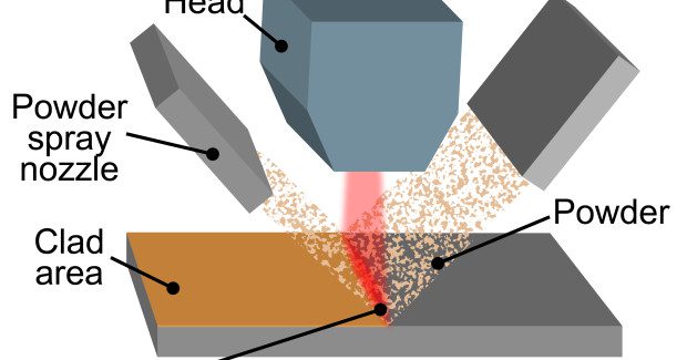
The line beam output from the high power diode laser is well suited to most metalworking applications, since it can be swept across the part to enable rapid processing of large areas. For example, in the case of powder-based cladding, the long axis of the line beam is oriented perpendicular to the direction of beam travel, as shown in the drawing. With a beam length of 24 mm, for example, a single pass “effective” clad width of 20 mm can typically be achieved (see Figure 1).
HIGH POWER DIODE LASER CLADDING ADVANTAGES
In some ways, high power diode laser cladding combines the best features of both arc welding and thermal spray methods. When compared to arc welding methods, diode laser systems offer lower heat related distortion, reduced dilution, extremely low porosity and better surface uniformity. Together, these properties substantially reduce the need for post-processing and its associated time and cost.
The high quench rate of the diode laser process also produces a finer grain structure in the clad leading to better corrosion resistance. Moreover, these benefits are generally not significantly negatively affected as laser power and deposition rate increase. In contrast, for most arc welding processes, clad quality suffers with increasing power and deposition rate. Finally, the line beam shape can process large areas rapidly with a high degree of control over clad width, thickness and deposition rate.
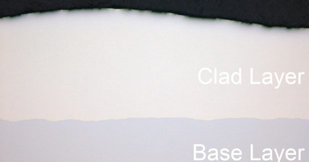
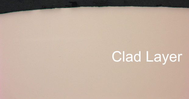
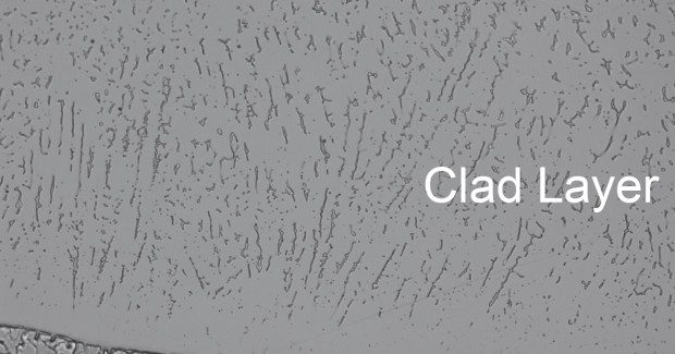
Both the diode laser and thermal spray techniques avoid significant heat input into the part and minimize dilution. This low level of dilution (~ 4 percent to 7 percent) typically supports the attainment of the desired surface chemistry for the clad deposit in a single cladding pass, thereby minimizing process cost. Unlike thermal spray, diode laser cladding forms a true metallurgical bond with the base material. The result is better adhesion and wear resistance. Furthermore, metallurgically bonded clads produced with the diode laser limit the cracking and de-lamination sometimes associated with mechanically bonded coatings. The microstructure photographs demonstrate some of the most desirable features of laser cladding (see Figures 2, 3, 4).
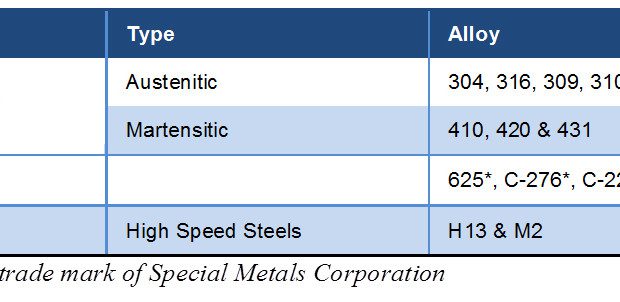
The diode laser cladding process is also compatible, and frequently used, with standard alloy materials commonly available in powder form (see Table 1). These include a wide variety of standard stainless steels, tool steels and corrosion- and heat-resistant nickel alloys. Most importantly, because of the low dilution and other attributes obtained with laser processing, the clad material exhibits a chemical composition having the characteristics of the original bulk material. This is important, because it means the clad layer will behave predictably, with the same desirable and expected properties of a bulk sample of the same alloy.
In contrast, this is not generally true when using powder with welding and flame spray deposition techniques. Clad properties can deviate from those of the original powder because of dilution and porosity in the clad layer.
Furthermore, flame spraying tends to rely on less common alloy systems that have been developed specifically for these application methods. Examples are be self-fluxing nickel alloys and special carbide bearing cobalt base alloys. Since these alloys are not common in bulk form (wire, rod, sheet, and plates), their properties are less well-known to those who select materials.
The fact that the material properties for laser clad layers are more familiar to users will eventually favor the use of this technology in an increasing number of industrial applications. The lower dilution of laser cladding as compared to arc welding methods also allows the desired results to be achieved with fewer clad layers. For example, when TIG or MIG welding IN-625 (a trademark of Special Metals Corporation), the desired iron content in the clad layer might be specified to < 5 percent, or, in certain cases, to < 10 percent. Due to the high dilution experienced with these welding techniques, a large number of cladding layers must typically be deposited before this low dilution level can be reached.
In contrast, dilution levels below even 5 percent can be achieved in a single layer with laser cladding (even lower dilution can be reached, but this might involve inadequate melting of the bulk material and therefore may not create a true metallurgical bond). The benefit of this is reduced cost. Specifically, a single layer clad takes less time to produce than a multilayer clad, and also uses less cladding material.
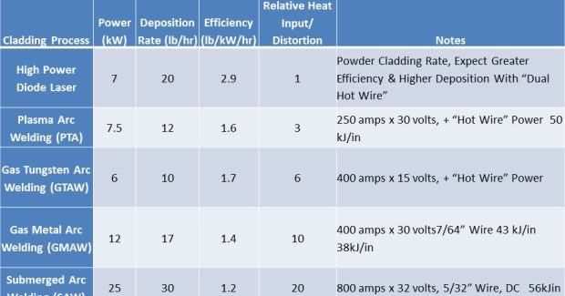
The limitations of high power diode laser cladding are mainly practical in nature. Specifically, the initial capital cost is higher than other cladding techniques and the physical size of the equipment can make it difficult to integrate into some production settings. Additionally, in some cases, laser cladding doesn’t support the deposition rates achievable with arc welding (albeit usually with a sacrifice in clad quality for fast arc welding). Table 2 compares the key parameters of laser diode and arc welding cladding processes.
In conclusion, the particular optical and operating characteristics of high power diode lasers now make them an excellent match for cladding applications. Specifically, they can produce clads of high quality and with a wide range of materials which already have good market availability and documented service performance. In particular, laser processing meets the increasing need in the market for cladding with standardized alloys. The superior integrity of the laser clad coating with standard alloys delivers results that, to a higher degree, conform to the principle alloy, resulting in more predictable performance.
In addition, laser cladding can be accomplished at relatively high deposition rates and usually only requires a single layer, making it a fast process. These factors, together with low heat distortion which substantially reduces the need for post processing, makes high power diode laser cladding cost competitive with traditional arc welding and thermal spray methods.
Subscribe to learn the latest in manufacturing.

Industry News


