Laser Beam Delivery and Focusing Optics
Some tips and best practices for maintaining a high production yield in micro welding.
Posted: March 5, 2014

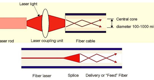


Most system integrators will usually provide the correct space within the workstation, but it is important to note that cable management from the workstation to the laser is the responsibility of the end user. It is also worth noting that increasing the length of the fiber does not result in a significant decrease in delivered power as the delivery of the laser through the fiber is very efficient. The main power losses occur at the fiber’s entry and exit from the laser. If the fiber’s entry and exit ends do not have an anti-reflective coating, power losses can be up to 2 percent to 3 percent at each end.
FOCUS HEAD AND OPTICS
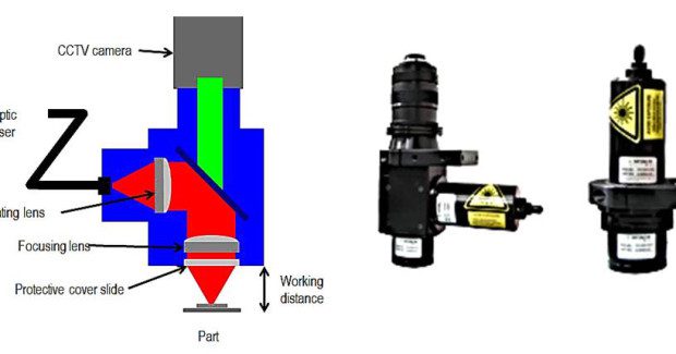
Select the right focus head and optics for space, working distance, part access, and tooling accommodation. With each focus head style, the laser diverges from the fiber cable and is “collimated” by a first optic, transforming the diverging light to light that is propagating parallel to the travel direction. The second lens, known as the focus lens, focuses the laser to a spot where processing will occur.
There are a number of different types of focusing heads. Figure 3 shows a few options, including a schematic of a 90 deg focus head, showing the collimating lens, the 45 deg reflector, focusing lens and cover slide; a 90 deg focus head; and an in-line focusing head. Selection will be based on the application, space and budget.
A great benefit of using one micron wavelength lasers is that these allow an in-line camera to be mounted to the head, providing a view of the weld area. By use of cross hairs pre-aligned to the position of the laser on the monitor, the operator can see the laser’s position laser relative to the workpiece. A key factor in welding is the laser-to-joint alignment, and with this type of head operators can make small positional adjustments so the laser correctly aligns to the joint.
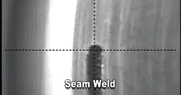
The adjustment can be made manually or can be automated using a vision system, which removes the operator from the equation and can increase accuracy. However, vision cannot always be used, due to part geometry. Also it is possible to vision-adjust in the XY and rotation but not in the Z axis. Figure 4 shows a view of the workpiece, with the cross hairs indicating the focus beam location. This can be used for either manual or vision-based laser-to-joint alignment.
Another great benefit of the in line camera is that the focus of the camera can be set to that of the laser, therefore if the camera image appears out of focus the laser will also be out of focus.
Where space is a big concern, the in-line head without camera option offers a solution that can work well for lap welds that have much larger fit-up tolerances, such that the camera is not essential for laser to joint alignment verification.
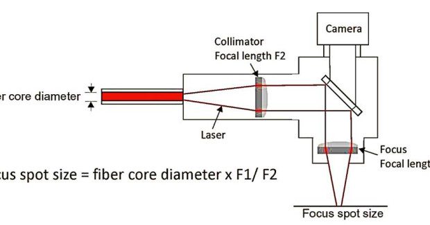
Knowing the optical spot size is an important part in creating the weld size needed for the parts and to accommodate any fit-up tolerances. As shown in Figure 5, the optical spot size is a function of the core diameter of the fiber and the magnification of the focus head, defined by the ratio of the focus lens to the collimator lens. The optics in the focus head effectively images the end of the fiber.
For example, a 400 micron fiber with a 100 mm collimator and 100 mm focus focal length produces an optical spot size of 400 microns. Note that the actual size of the weld is usually larger than the optical spot size and can be fine-tuned using pulse width for pulsed welding and speed for continuous wave seam welding.
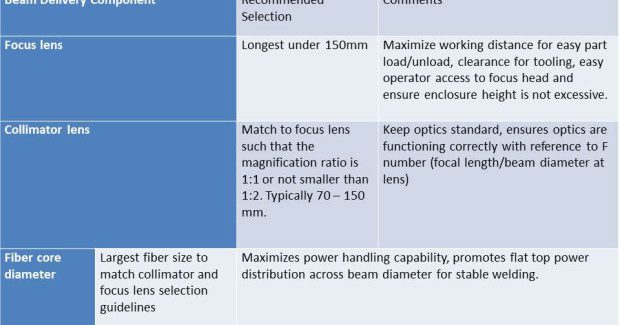
Selection of the fiber diameter and focal lengths for the collimator and focus lens may seem limitless, but be sure to follow these simple rules:
- The focal length should be maximized to provide sufficient working distance.
- The magnification ratio should be 1:1 (x1) and no less than 1:2 (x0.5).
- The largest core diameter should be selected to ensure the first two rules.
Table 1 summarizes the selection considerations.
Preventative Maintenance
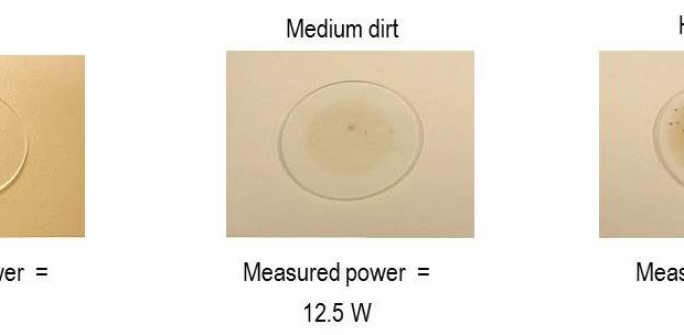
Be sure to clean the lens cover slide, and replace it as required by the particular process, because contamination may lead to power transmission loss. For non-critical welds a loss of 5 percent is not significant, but heavy dirt on the cover slide can lead to a 10 percent power loss, and this is a problem. Figure 6 shows the effect of contamination on transmitted laser power.
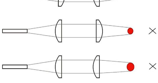
The focus optic and the collimation optic may need replacing over time, and make sure you ensure the correct lens orientation when returning cleaned or new lenses. The lenses have a curved shape on one side and a flat on the other, and the efficiency of lens and the resulting optical focus spot size and focus position are affected by the lens orientation.
Figure 7 shows how changing the specific orientation of the collimator and focus lens can change the optical spot size.
Manufacturing engineers who use the best practices discussed for beam delivery and focus optics will be able to benchmark and troubleshoot the optic side of the laser system equation. Knowing what can go wrong, conducting preventive maintenance, and developing a benchmarking testing plan, are all steps that can be taken to maintain a high production yield. Gaining familiarity with the beam delivery and focus optics part of the system will empower engineers to have “24 / 7” coverage of their system and give them the tools they need to know what to do if something goes wrong.
Subscribe to learn the latest in manufacturing.

Industry News