CAD/CAM Sheet Metal Fabrication Software: The Latest Trends and Advances
These new systems showcase how CAD/CAM software for sheet metal and structural steel fabrication is coming of age to meet the increasing needs for speed in job shops, contract manufacturers and metal service centers.
Posted: April 23, 2014


DIE SET CONFIGURATOR
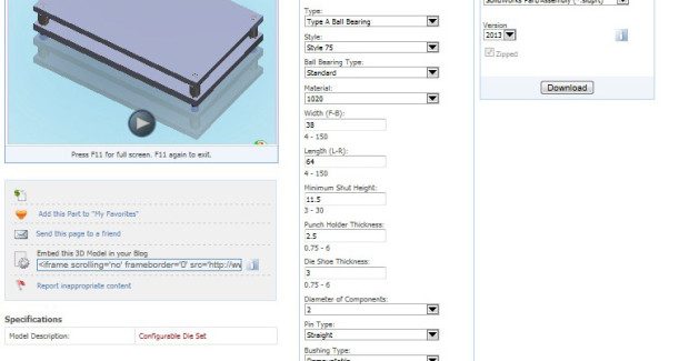
Superior Die Set Corporation (Oak Creek, WI) introduces a ‘die set’ configurator available through their 3D CADlink system. This innovative CAD drawing generator creates a customized die set rendering for easy downloading in your native application. Once completed, the 2D or 3D rendering includes all the plates and components of a die set. The user then chooses the format and version to download the image to their computer.
Access to the 3D die set configurator is made either through: the Superior Die Set home page and click on 3D CADlink, the digital edition Master Catalog die set rendering button, or scanning the appropriate die set QR code.
The die set configurator automatically generates optional component lengths but defaults the longest available to maximize pin and bushing engagement. You can shorten these lengths, but not choose any that may crash the die. Upon completion of the rendering, simply click on the “Request for Quote” button to automatically send the die set specifications directly to Superior for fast quotation processing. The 3D CADlink system also stores the complete line of die set and mold base components for easy downloading. The system is free of charge and only requires a one-time registration. Stay abreast of 3D CADlink updates by liking us on Facebook or visit our home page.
Superior Die Set Corporation, 900 West Drexel Avenue, Oak Creek, WI 53154, 414-764-4900, Fax: 800-657-0855, www.supdie.com.
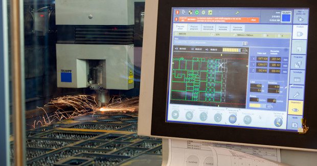
EXTENSIVE ARRAY OF PROCESS SCHEDULING AND MONITORING FUNCTIONS
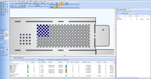
High-performance software is fundamental to modern sheet metal processing. BySoft 7 from Bystronic Inc. (Elgin, IL) is a robust CAD/CAM software package that supports both 2D and 3D CAD and provides the user with an extensive array of process scheduling and monitoring functions. According to Robert St. Aubin, the president of Bystronic, “BySoft 7 is not simply an update. Rather, it is a completely next generation of design and manufacturing software generation, with a wide range of new functions that offer a host of possibilities. We market BySoft 7 with the slogan ‘Make it easy’, and users will find that it delivers fully on this promise.”
This software incorporates the latest version of SolidWorks, one the industry’s most popular and respected 2D and 3D CAD packages. Users can quickly and easily design custom parts, and input existing drawing and models for editing and processing.
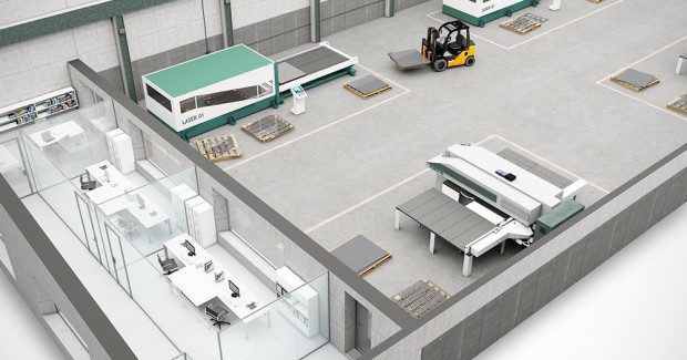
BySoft 7 employs a highly intuitively structure that enables first-time users to begin working with the software quickly and easily. It consists of four modules: Sheet Processing, Tube Processing, Bending, and Plant Manager. Plant Manager is a unique operational tool that both plans and monitors manufacturing processes, including all laser and waterjet cutting operations. Moreover, Plant Manager compiles all relevant machine and production data and makes it continuously available to the operator, providing maximum transparency for both sheet and tube processing.
Bystronic Inc., 200 Airport Road, Elgin, IL 60123, 847-214-0300, www.bystronicusa.com.
AUTOMATIC SHEET PROCESSING
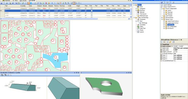
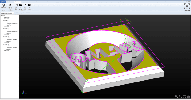
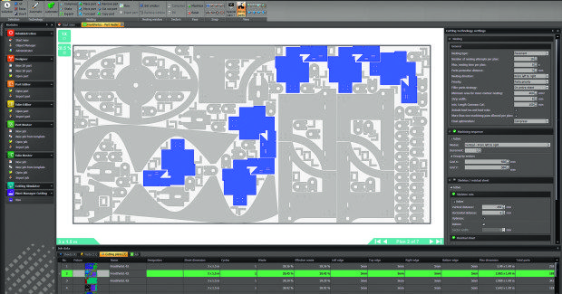
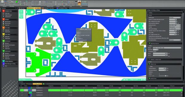
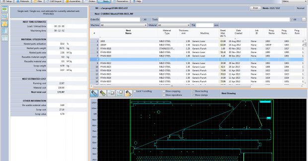
JETCAM International s.a.r.l. (Monaco) showcases its flagship nesting product, JETCAM Expert, with a completely revamped interface along with a raft of new features covered under the title of Automatic Sheet Processing. This includes processes such as new internal destruction routines, common punching and much more. New runtime estimation algorithms further improve accuracy for quoting, and bevel support for profiling machines has also been added. A new version of Expert, called Premium Connected Automation (CA), allows any system such as an MRP/ERP software to remotely control JETCAM. Functions such as automatically importing CAD files to create tooled components, or automatic nesting for different machines and materials can all be performed remotely and automatically.
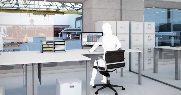
The sheet metal specific version of the CrossTrack manufacturing suite provides complete visibility of orders/material stock/nests/machine workloads and full traceability, delivering reduction of errors and massive time savings. Paper can be massively reduced or, in many cases, eliminated. All information is updated in real time across the network, so all staff are working from the same live data. Barcode scanning removes the possibility of error, and the need to enter data across different systems is eradicated. CrossTrack works in conjunction with JETCAM Expert nesting software to provide true dynamic high performance nesting, which alone can often pay for the system within months.
JETCAM Orders Controller (JOC) is now available in three versions: JOC Lite, Premium and Premium Automation. All versions provide a simple way of remotely populating JETCAM Expert’s orders list.
JETCAM International s.a.r.l., “Milenium” 9C, 9 Boulevard Charles III, Monaco MC98000, +44 (0)870 760 6469, www.jetcam.com.
SOMETHING FOR ALL
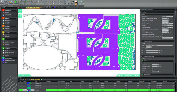
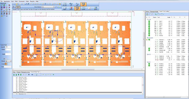
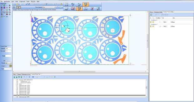
Sheet metal specialists Radan Software/Vero Software Limited (Gloucestershire, England) offers Radan 2014, which incorporates a host of new and enhanced functionality including 3D workflow improvements, safety measures to prevent tipping on flat-bed lasers, along with strides in common cutting on punches, and support for cluster and asymmetric wheel tools.
“Whether a defined sequence is used automatically, manually or interactively, the simulation now comes from there. In previous releases, the user had access to far less information than the software actually holds about the tools, the machine and the accelerations that are possible,” says product manager Olaf Körner. “Changing the location of these two functions means that every machine tool using the simulator benefits from the improved graphics, increased feedback and overall knowledge that the sequence mode has.”
Enhancements to 3D Workflow dramatically reduce the time taken to get parts to the nest. Previously several manual steps were required including unfolding the model, saving as a part and adding the right quantity to the schedule. Now all sheet metal, whether single or assemblies, is unfolded and added to the nest area automatically. This reduces the number of mouse clicks for single parts from around 26, down to just three or four – a massive time saving that also reduces the possibility of errors.
There are enhancements for asymmetric wheel tools as they are becoming more popular in offering alternative strategies to secondary operations for both cutting and forming. As soon as you purchase a wheel tool, you can now look it up in Radan, add it to your master tool file, and everything is then set up for it, including graphical feedback when it’s applied.
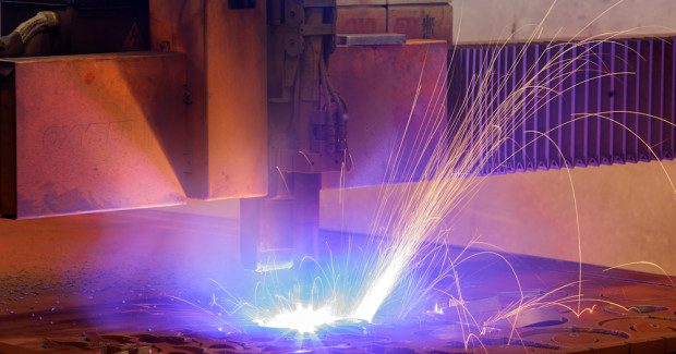
Scrap internal profiles: This safety measure has been introduced to avoid head collisions on flat-bed lasers, and is achieved by cutting profiles that are in danger of tipping, into smaller pieces before cutting the final shape. Instead of cutting it in one go, the software now cuts a grid across it first, and the small parts of the grid simply fall away when the final profile is cut. The same common cutting strategy is adopted for punch presses as that used for profiling machines. It allows for common cut nests to be created automatically, meaning the user can choose, for example, how many parts form a common cut island, reducing the sheet’s instability. Tagging for common cut parts has also been improved. “With the absence of a skeleton – which is inherent to common cutting – the tag placements must be absolutely right,” notes Körner.
Other features include:
- A faster, more efficient and risk-free way of updating 3D translators is introduced.
- Visualizing geometry is made clearer by dividing the screen into two halves. The main geometry is shown on one side, while the other side summarizes the topology of the part. For example, if all the bends are selected, the summary screen updates those.
- Drawing patterns: Where third-party geometry files may be over-complex and difficult to navigate, Radan 2014 now displays information in a clear way, making it easy to work through the drawing. The user can extract just the information that’s relevant to the cutting process.
Vero Software Limited, Hadley House, Bayshill Road, Cheltenham, Gloucestershire, GL50 3AW England, www.radan.com.
EXTRACT AND GENERATE TUBE BENDING DATA IN SECONDS
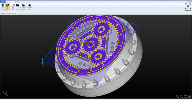
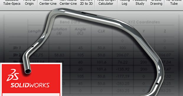
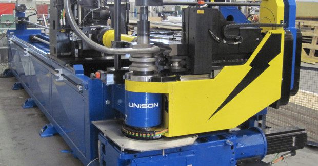
An innovative PC-based CAD/CAM solution for tubular metal fabricators who use SolidWorks CAD software, that enables them to reduce order processing and pre-production development time from hours to minutes, has been launched by the tube bending machine builder Unison Ltd. (Scarborough, UK) through its exclusive U.S. distributor Horn Machine Tools (Madera, CA).
The software automatically extracts key manufacturing information, including tube specifications and CNC bending data, from both native SolidWorks models and common CAD file formats such as STEP, IGES, and ParaSolid. It can handle tube models with round (tube and bar), square, rectangular, oval or flat-sided oval cross-sections. Unison has secured exclusive worldwide sales for the new software add-in – called TubeWorks – from its developer, 3DCompound Ltd.
3DCompound, a UK-based software consultancy, specializes in the development of third-party value-added products for the highly popular ‘SolidWorks’ mechanical design software. The company was founded by an accredited SolidWorks Elite Application Engineer with an extensive background in CAD and tube bending technology. It produces a variety of innovative software tools, ranging from macros to fully integrated add-in modules, which enable SolidWorks users and their organizations to realize major savings in the time and capital cost of application-specific processes.
According to Alan Pickering, the managing director of Unison, “Automating the extraction of manufacturing data from CAD files helps bending machine users to create production-ready programs much more quickly and efficiently. TubeWorks provides users with an enormous competitive advantage and is an important addition to our growing portfolio of software tools. As well as offering a smart solution for metal fabricators seeking to accelerate their request-for-quotation (RFQ) procedures, the software will help shops with in-house bending machines to reduce design-to-manufacturing times.”
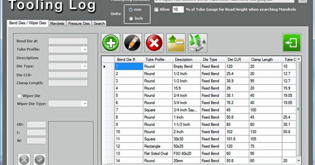
The TubeWorks add-in is fully integrated into SolidWorks, allowing users to take full advantage of the CAD software’s powerful design functions, and eliminates the need for any additional standalone solutions for generating manufacturing data during the design, development and production of tubular parts. The add-in software is inherently intuitive and easy to use, requires no special training and can be mastered within 10 minutes. The software also extensively automates the generation of 2D drawings, as well as the creation of reports for the YBC data that will be used to control the bending machine and for the XYZ coordinates of the modeled tube.
Horn Machine Tools, 40455 Brickyard Drive, Madera, CA 93636, 559-431-4131, www.hornmachinetools.com.
Subscribe to learn the latest in manufacturing.

Industry News