Getting to True Position in Six Degrees of Freedom
The new nanometer level of precision being achieved by next generation motion systems to meet the high precision demands of metrology, laser processing and micro-machining opens up a whole new realm of application possibilities. This white paper examines how it works.
Posted: July 30, 2014
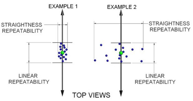


While there are compensation methods to reduce error sources in conventional 6-link hexapods, they do not improve performance at the single-digit micron or nanometer level. Motion systems’ straightness and repeatability performance must be analyzed and specified using a point precision methodology that accounts for all 6-D spatial errors in order to provide a true representation of nanometer precision, or True Nano precision.
HYBRID HEXAPOD ADVANTAGES EXPLAINED
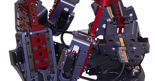
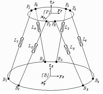
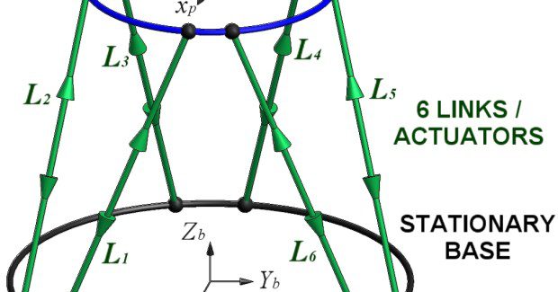
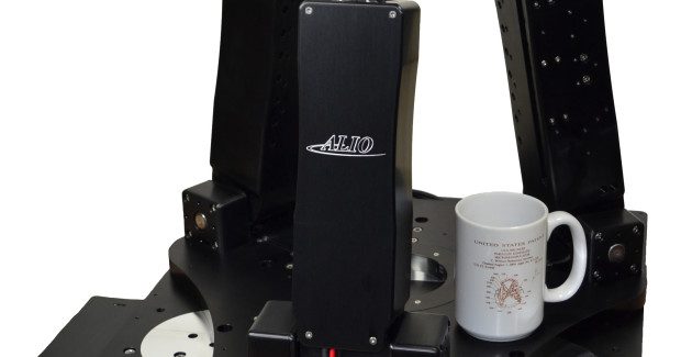
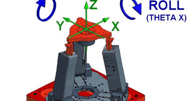
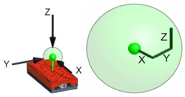
The Hybrid Hexapod® was developed by ALIO Industries (Wheat Ridge, CO) to address the critical weaknesses of conventional legacy hexapod designs as outlined above, as well as the weaknesses of stacked serial stages, and to achieve nanometer accuracy, repeatability, and high-integrity flatness and straightness during motion. The name Hybrid Hexapod is indicative of a 6-DOF function motion positioning system constructed of a hybrid serial and parallel kinematic structure, rather than a six-link pure parallel kinematic design structure (see Figure 2).
It utilizes a tripod parallel kinematics structure to deliver Z plane and tip/tilt motion, integrated with a monolithic serial kinematic structure for XY motion. A rotary stage integrated into the top of the tripod (or underneath it depending on application needs) provides 360 deg continuous yaw rotation. In this hybrid design, individual axes can be customized to provide travel ranges from millimeters to over one meter, while maintaining nanometer levels of precision
This hybrid structure is designed for unprecedented precision performance at the nano-scale level, with significant improvements over conventional hexapods in the following critical aspects:
LINK DESIGN
Each link of a common hexapod works in coordination with the other links to position the top platform or user mounting surface. The precision of the top platform is a direct consequence of the precision of the individual links. While link designs for hexapods come in many forms and technologies, the fact that they are oriented vertically and work against gravity has led to design decisions and restrictions that prohibit achieving True Nano precision performance.
Specifically, some manufacturers simply use an off-the-shelf linear actuator as the link in a hexapod. As the hexapod moves, the forces on each joint end of the actuator will vary in magnitude and direction, and often the actuators were not originally designed to handle such varying loads and still maintain the cantilevered joint location in space with high precision.
MOTION TRAJECTORY/ STRAIGHTNESS
With any motion system, if you command motion in a straight line, industry standards define “straightness” as the measure of deviation of the actual motion away from the perfectly straight ideal path. All motion systems will have these “straightness” errors, and the pertinent question to most motion system end users is, how large are those errors and do they negatively impact the application, measurement, or process? Non-straight motion trajectories can also be analyzed to determine how closely a commanded free-form path can be followed. Is a commanded circle actually a circle or is it an oval or a three lobed shape?
From a motor perspective, the consensus has been to use either rotational motors attached to a ball screw (or micrometer lead screw) or use a friction motor (typically piezoelectric) to drive the link linearly. This is because the mechanical advantage or friction of the motor helps the motor support the load against gravity. That capability is the motor’s inherent weakness, such that it is the motor that supports the payload against gravity and thus the load on the motor varies with the angle of the link and whether the link is moving upward (against gravity) or downward (with gravity).
Any precision engineer will tell you thermal gradients or heat sources are the enemy of precision. Varying motor loads directly corresponds to varying heat generation. Finally, many actuators have rotary encoders on the back of the rotary motors, or linear encoders on coupled linear directions, such that they measure one position and convert it, via calculations, to a link position. These designs introduce backlash and accuracy errors due to lead screw pitch errors and assumptions in the position conversion.
While it is possible to do advanced level calibration of hexapods and add in external sensors to the platform, this is costly and time consuming, and still generally will not get performance below the 10 seconds of microns level.
The Hybrid Hexapod, however, has been designed to counteract the liabilities presented above, and enable optimum performance in several ways:
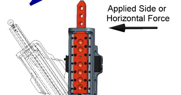
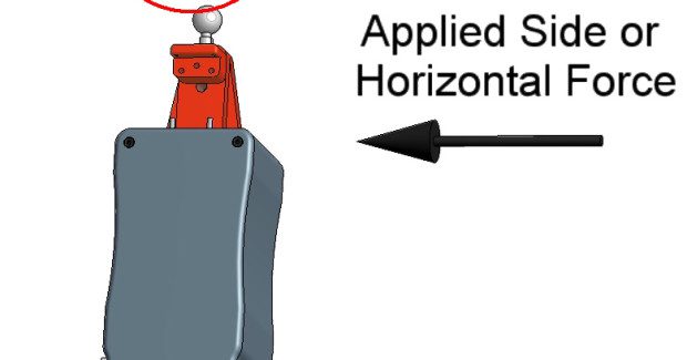
a) Its design utilizes a vertical brushless, linear servo-motor oriented along the link axis. Since linear motors are non-contact, there is no friction or wear, hence, very little heat is generated. Additionally the force axis of the motor is aligned with the linear axis of the link, so there is no mechanical coupling (as required with ball screws) that can introduce other error sources. Typically, designers have stayed away from this concept due to heat generation.
b) A near frictionless pneumatic or non-contact magnetic spring is employed on each strut, which zeros-out the strut load against gravity, allowing for high payload capabilities. Aside from the slight inertia of the payload, there is very little force that the motor needs to overcome to move the system, because the counterbalance supports the mass. The counterbalancing effect also ensures that whatever heat is generated by the motor stays relatively consistent.
c) A non-contact optical linear encoder that eliminates backlash and error sources common to rotary encoder systems. The link position sensor is positioned vertically, directly in the axis of motion, reflecting the highest precision of link placement coinciding with joint placement, and thus, the least amount of errors.
Subscribe to learn the latest in manufacturing.

Industry News