Another Look at Aerospace Machining
Competitors in this demanding hotbed of manufacturing are being pushed to find new ways of producing more complex parts. Here are some systems that can help them meet their needs.
Posted: September 10, 2014


USING ECM/PECM TO MANUFACTURE AIRCRAFT ENGINE COMPONENTS
According to a recent survey by Boeing, the number of aircraft deployed worldwide will double within the next 20 years. This will, of course, lead to an enormous increase in the number of aircraft engines required. It is not only the increasing demand for engines that pose new challenges to engine manufacturers, but also ever tightening environmental standards.
Three criteria characterize the demands on aircraft engine production. With increasing cost pressures and fierce competition, the market calls for engines with significantly improved fuel efficiency. Environmental regulations toughen demands for emission reductions. And there is a need to reduce purchase and maintenance costs of new aircraft engines. Fuel consumption and emission levels go hand-in-hand and are, to a large extent, determined by the design of the various compression stages of the engine. Every increase in efficiency brings with it a reduction in fuel consumption and, in turn, CO² emissions.
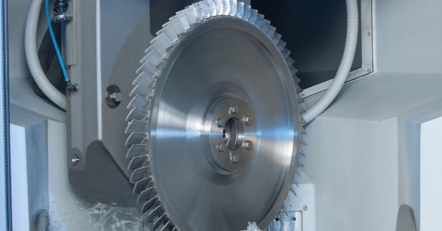
An increase in speed leads to an increased compression ratio between the various compression stages and to the desired increase of thermal efficiency. This strategy will, at the same time, bring about a reduction of the required number of blades, which allows for an optimal aerodynamic design of the individual blades. Higher speeds and temperatures exert increasing pressure on the compressor rotor, which must be taken into consideration when opting for an integral design where the mechanical connection between blade root and disk disappears and the rotor is produced as an integral component (blisk = blade integrated disk).
This ensures that the high loads on the blade root are absorbed by the entire disk, then removes the mechanical connection between the two components so the integral design provides for a mass-reducing construction that offers greater economic viability.
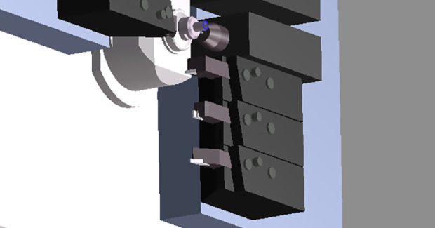
http://youtu.be/OAfrv6g0Usk
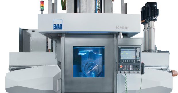
A demonstration of the EMAG PO 900 BF.
In the past, the choice of material used in such cases fell to nickel-based alloys because the high operating temperatures in the high-pressure compressor environment had to be taken into account. The effort to satisfy the ever increasing demands for higher temperatures and a reduction in component weight has, for some time, concentrated on the use of titanium alloy replacements. Development in this area has advanced significantly, with materials reaching official safety class 1 approval in the “rotating components” sector. These new alloys are even more difficult to machine in comparison, so it is imperative to find alternative production processes that satisfy economic and technological requirements for both materials.
All of this means it is critical to quickly introduce new processes for the production of those aircraft engines still in the development, especially when one considers the increasing requirement for blisk components over the next few years.
ECM Process
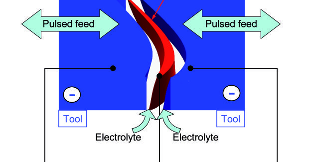
Electro-Chemical Machining (ECM) is the removal of metal through electrolysis. The work piece is polarized positive (anode) and the tool negative (cathode). The working gap is flushed with a conductive electrolytic solution. The introduction of voltage leads to the molecular erosion of the work piece material. The material removed, metal hydroxide, is flushed out and separated from the electrolyte by a filtering system. The electrolyte is then reused in the process.
The ECM process is most commonly associated with deburring applications, especially in injection technology, where specially designed tools were used to remove material only at strictly localised points – to remove burrs or for the creation of radii. ECM has also been used to create annular grooves, cavities and other geometries.
Using 2.5D imaging technology and DC generators also allows ECM to be used for the countersinking process, however, either the quality of the image proved mediocre or the development costs for the tools to achieve the desired geometry were too high. But, where the results fulfill the requirement, reproducibility of the process is effective, tool wear is minimal and the hardness of the material has no negative influence on material removal rates. If the machining surface for the cathode is increased, the process does not lengthen the cycle time.
PECM process
With the subsequent development of the ECM process into PECM (Precise Electro-Chemical Machining), it became possible to increase the accuracy of the geometries and reduce the development costs involved in achieving the required final results. To achieve precise work piece geometry, the machining gap is narrowed down considerably. The exchange of electrolytes along with mechanical oscillation in conjunction with feed rate and a pulsed current/voltage source ensures optimal high quality surface finishes.
In the generation of blade geometry and blisks, both sides of the work piece are machined simultaneously using a synchronized oscillating action. The monitoring and adjustment of voltage, current and electrolyte flow offers optimal process integrity. Generator technology plays a particularly important role in monitoring working gap, changes in current and fast-action short-circuit shutdowns. Along with an operator-friendly integration of the process parameters, this technology is sure to become the most widely accepted and innovative manufacturing process for the generation of blade and blisk geometry for the future of aircraft engine manufacturing.
The major advantages of ECM/PECM are:
- Machining of high-tensile alloys
- Minimal tool wear
- High degree of Accuracy
- Excellent surface finishes
- No resulting burrs
- Thermally neutral process has no negative effect on the material
- No recast layer
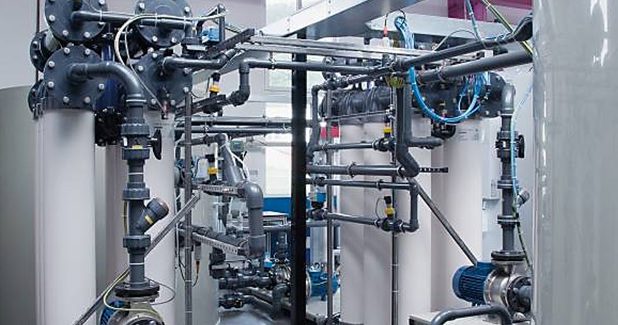
An electrolyte management system ensures that the quality (pH and conductance, temperature and purity) of the working medium remains constant at all times. This can be achieved with various filtration techniques (gravity filtration, chambered filter presses, microfiltration), depending on the machining requirement.
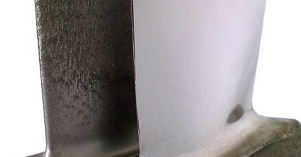
For the machining of both single blades and blisks, roughing and finishing operations are recommended. The rough machining process is a pre-contouring operation with open tolerances and feedrates of 2 mm/min to 4 mm/min, while leaving enough material for the subsequent finishing process (approx. 0.2 mm). The rough machining operation can be carried out using a variety of tooling strategies economically optimized to suit the relevant geometry. Where the single blade may be machined with a double-sided, synchronized operation, the pre-machining of blisk geometries are best done along the blade axis.
The ECM process offers a competitive advantage in the tool geometry and the suitable scaling of the power supply allowing large blades and blisks to be machined at the same feed rates and the same cycle times as smaller single blades. With scalable power supplies and generator technology, the whole installation is easily adjusted to suit user requirements and remain economically viable.
ECM/PECM technology from EMAG LLC (Farmington Hills, MI) covers a power range of up to 20,000A DC and a pulse rate of 30,000A. The machine can accommodate work pieces of 900 mm maximum diameter and single blades up to 250 mm in height. For engine components, EMAG relies on the latest developments of the tried and true PO 900 BF machine platform, on which roughing and finish-machining operations can be carried out on large single blades and blisks alike. These machines can also be equipped with hydraulic zero-point clamping systems, variable oscillators and automatic tool changers.
This technology offers the marketplace unique cohesion in the machining of engine components. Their expertise covers everything from process and tool development to the machine, power electronics and filtration, giving manufacturers the opportunity to enter into the technology with a strong partner at their side.
EMAG LLC, 38800 Grand River Avenue, Farmington Hills, MI 48335, 248-477-7440, info@usa.emag.com, www.emag.com.
ECONOMICAL GANTRY BORING AND MILLING OF LARGE PARTS
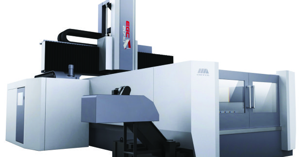
To provide value to U.S. manufacturers in aerospace, SMTCL USA, Inc. (City of Industry, CA) has introduced a re-designed large Gantry Boring and Milling Center, the EGC2040, that provides increased reliability and performance to manufacturers of large parts. “Our engineers in Germany reduced the number of components on the machine, which has both increased the machine’s reliability and decreased the cost,” states SMTCL chief operating officer Jerry McCarty. “By focusing on design and quality, we are able to provide our customers a better product at lower price.”
The table on the EGC2040 is 78 in x 157 in and capable of handling 30,800 lb. Travels on the machine are 165 in X, 88 in Y, 31 in Z. The machine is controlled by the powerful FANUC 0i-MD control with a 10.4 in screen, USB, PCMIA and Ethernet capabilities, AICC II, and a Remote Manual Pulse Generator.
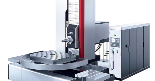
SMTCL-Americas has also introduced the new EBC110 table-type boring mill that will allow manufacturers of large aerospace parts to compete at new levels. The machine was designed in Germany and utilizes the latest industry technology combined with years of experience from two recognized boring mill leaders: Schiess and SMTCL. As McCarty points out, “The result is an ultra rigid, extremely powerful, highly accurate, and reliable boring mill.”
To ensure accuracy and repeatability, the EBC110 features German-made Heidenhain scales on the X, Y, and Z axes and a precision 49 in x 55 in full B-axis rotary table capable of holding 11,000 lb. The machine is a box way design with travels of 78 in X, 59 in Y, and 47 in Z. The machine also features a spindle quill that provides an additional 21 of W-axis travel. This CNC boring mill is controlled by a FANUC 0i-MD Control with 10.4 in screen, USB, PCMIA and Ethernet capabilities, and a Remote Manual Pulse Generator. “The reliability of FANUC, Heidenhain, and SMTCL components will allow this machine model to perform accurately for our customers for many years,” adds McCarty.
SMTCL is the largest machine tool manufacturer in the world, producing 80,000 machine tools each year, with revenues of $2.9 billion. The company has over 300 products, including CNC boring mills, vertical turning centers, vertical machining centers, horizontal turning centers, horizontal machining centers, gantry type machining centers, pipe threading machines and tapping centers, as well as conventional lathes, boring mills, and radial drills. The company has design centers in Berlin, Germany and Shanghai, China, as well as multiple factories in Germany and China. The SMTCL-Americas Technology Center that is located in City of Industry stocks machines, replacement parts, and accessories.
SMTCL USA, Inc., 17038 E. Gale Avenue, City of Industry, CA 91745, 626-667-1192, Fax: 626-667-1197, www.smtcl-americas.com.
SUPER-FINE LASER CUTTING AND ABLATION OF SUPER-HARD MATERIALS
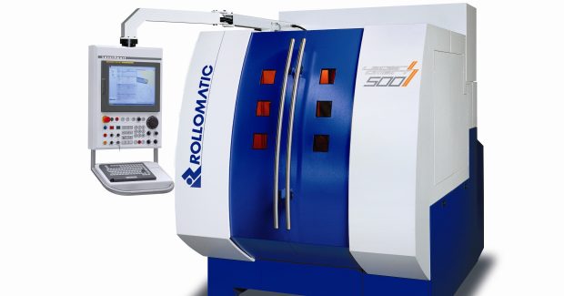
In response to an increasing demand from the aerospace industry for high performance cutting tools, Rollomatic, Inc. (Mundelein, IL), a leading machine tool manufacturer based in Le Landeron, Switzerland, has added the LaserSmart® laser cutting/ablation machine to its portfolio of conventional grinding techniques.
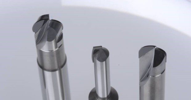
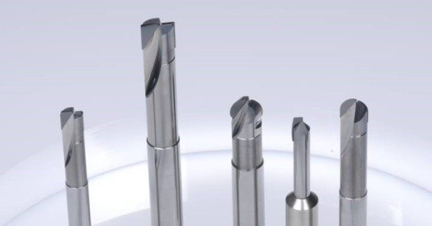
The initial strategy for this machine is to offer a more cost-effective way and higher quality in the production of high-performance PCD (polycrystalline diamond), CBN (cubic boron nitride) and CVD (chemical vapor deposited) cutting tools which are traditionally required to be manufactured by a double process of spark erosion and polish grinding.
Fine-laser cutting achieves a superfine cutting edge with a surface finish that is unachievable by grinding/EDM. Conventional grinding with diamond wheels will invariably “pull out” entire PCD crystals, but laser cutting slices through the crystal and leaves a portion of the crystal in the matrix to attain a super-sharp cutting edge that is unattainable by EDM, EDG (electro-discharge) or grinding. Linear technology used on the linear and rotary axes provides highly accurate trajectories for the complex cutting paths.
Continuous testing over the last four years have shown that sharper cutting edges and superior surface quality on PCD tools deliver longer tool life and higher feed rates during machining. Laser ablation allows the freedom to optimize tool geometries. Manufacturing chip form geometries in PCD are easily performed by the LaserSmart® using the ablation process as a cost-effective and powerful alternative to existing complicated and expensive conventional methods.
Subscribe to learn the latest in manufacturing.

Industry News