Don’t Get Left Behind
Shops everywhere are investing in 5-axis machining technology to increase profit margins on parts they were producing on 3-axis machines. Here’s why.
Posted: June 18, 2015


CNC technology continues to accelerate. It’s difficult to figure out what matters and what doesn’t when it comes to new features and new processes. Technology surrounding 5-axis machining can be even more difficult to digest, especially if you don’t have a 5-axis machin- ing center yet. This technical article distills the massive amounts of technology jargon to explain software features resident in a 5-axis machining center’s control that make the process more efficient. We will also illustrate why shops all over the country are investing in 5-axis to increase profit margins on parts they were producing on 3-axis machines.
PROBLEM MULTIPLE PART-ZERO SETUPS
Even an uncomplicated part that is five-sided requires multiple part-zero setups. You waste time and compromise accuracy when you have to continuously flip the part to machine each side. Doing the same part using a five-sided process turns five setups into one.
SOLUTION: TRANSFORM PLANE
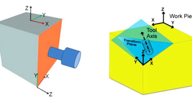
A software feature called Transform Plane (see Figure 1) simplifies five-sided programming and eliminates the hassle of setting up part zero five times. The technology does the work so you can start making chips. You just need to locate one part zero and the remaining part zero locations can be defined as incremental measurements from the original location.
Additionally, you can still program the geometry on each of the sides if you’re programming in an XY plane. Transform Plane basically changes programming on a 5-axis mill back to 2.5D programming that you would do on a 3-axis mill — you don’t need to worry about the tilting or rotating. How it works: The tool axis becomes the Z-axis. The control calculates all the tilting and rotating required.
PROBLEM: REDUNDANCY IN POSTING A 5-AXIS PROGRAM
Each time you re-fixture, you waste valuable time re-entering the distance from part zero to the centerlines of rotation and then reposting the program.
SOLUTION: TOOL CENTER POINT MANAGEMENT
If your control has a software feature such as tool center point management, you only have to post the program once and machine the part — no matter where it is in relation to the center lines of rotation on the machine (see Figure 2). Tool center point management solves the problem for CAM software. The CAM programmer generates the toolpath based on the part model’s zero location. Therefore, you can post the program independent of where the stock is fixtured on the table — a substantial time saver for a 5-axis part. Benefits include faster setup, less complex post processor (NC), and time saved reposting the program (NC).
How it works: The machine coordinates are uncoupled from the part coordinates, which means you only need to find the top corner of the part and the machine knows where the machine position is located in relation to the centerlines of rotation.
PROBLEM: COMPLEX AND DIFFICULT POST PROCESSORS
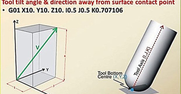
CAM systems generally use tool vectors to generate the toolpath. To make programs independent of the machine’s rotary configuration and to simplify the post processor, there is a tool vector input control software feature for 5-axis machining centers (see Figure 3).
SOLUTION: TOOL VECTOR INPUT
The Tool Vector Input feature lets you specify the tool tip location relative to the workpiece and the tool axis vector instead of using address letters to specify the B and C axes angles. Executing the program is much faster because the post doesn’t need the machine configu- ration and the centerline of the rotary axes. Tool Vector Input allows the control to compute machine angles and positions, and calculates the angle the tool is going to tilt from the contact point of the surface. Benefits include scheduling flexibility (the program can run on another 5-axis machine with a different axis configuration) and simplified post processing. Also, the control computes machine angles and positions.
How it works: Because CAM systems generally use tool vectors to generate the tool path internally, Tool Vector Input allows the machining center’s control to accept the vector code so the CAM system doesn’t have to filter the code through a post processor. The control lets you specify the tool tip location relative to the workpiece and the tool axis vector instead of using address letters to specify the A, B and/or C axes angles. The control’s software automatically compensates for the position of the tool using part coordinates that are relative to the centerlines of rotation for the B and C axes. Therefore, the control understands where the workpiece is located relative to the centerlines of rotation of the rotary axis.
PROBLEM: MARKS ON THE PART
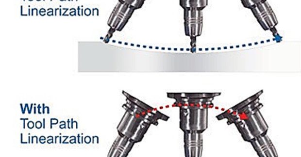
Simultaneous 5-axis toolpaths can result in odd looping rotary moves that leave marks on the part when the program is interpolated by the machine’s control.
SOLUTION: TOOLPATH LINEARIZATION
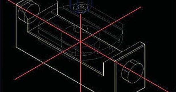
A feature called toolpath linearization, which is specific to 5-axis, G-code (NC) programs, eliminates the many line segments in the form of XYZBC or AC moves that a CAM system uses. Benefits include improved surface finish quality, smaller NC programs, and elimination of gouging of the workpiece. How it works: The tool tip and tool vector are interpolated between tool positions with respect to the workpiece, even with the tool and part rotating inside the machine. The tool tip basically attaches itself to the workpiece instead of blindly following the rotations commanded (see Figure 4).
PROBLEM: REPOSTING TO ADJUST FOR TOOL WEAR ON 3D SURFACES
For 3D surfaces, you cut off of the tool centerline to get a better surface finish. Oftentimes, you are forced to repost the program because you need to adjust the tool diameter for wear.
SOLUTION: 3D TOOL COMPENSATION
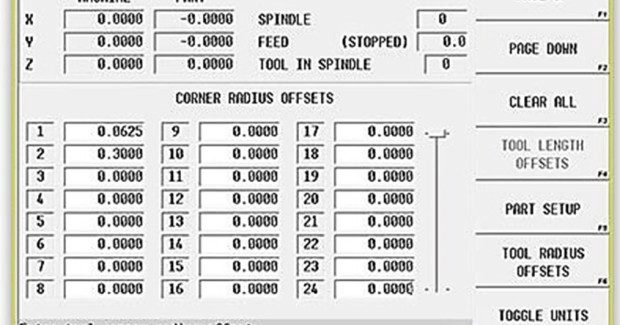
A software feature called 3D tool compensation eliminates the need to repost the program in order to adjust the tool diameter to compensate for tool wear or tool substitution. Benefits include the elimination of idle time caused by tool breakage, tool wear compensation, flexibility and freedom in tool selection, and saving significant time compared to rewriting the program to adjust for tool wear, tool breakage, and/or tool substitution, and then reposting the program.
How it works: The 3D Tool Compensation feature adds UVW, which is the surface contact point of where the radius comes in contact with the surface it is cutting. You only needs to change the D (diameter) and R (radius) values of the tool. The 3D Tool Compensation feature does the rest (see Figure 5).
LATEST + GREATEST FEATURES
Automatic Safe Repositioning (ASR) is a control feature only available from Hurco. ASR tells the machine to retract along the vector and override the out-of-limits protocol. No stoppage. No error message. The software is smart enough to retract, move to Z0 along the X-limit, re-orient the tool, move to retract plane, move above the plunge point, and plunge to the target along the tool vector. An addition of one G-Code tells the machine to retract along the vector and override the out of limits protocol. No stoppage. No error message. The software is smart enough to retract, move to Z0 along the X-limit, reorient tool, move to retract plane, move above the plunge point and plunge to the target along the tool vector.
Universal Rotary allows a part program to be used interchangeably on both types of Hurco 5-axis machining centers even though they have different configurations. You simply program how the tool rotates into position on the part, and the control instructs the machine how to orient the axis to cut the feature.
To watch a webinar that teaches more about 5-axis machining technology, please click here.
USER CORNER: 5 VS. 3
“The five-sided software is very easy to use. On our 3-axis machines we had six setups. On our new 5-axis VM10U, we only have two setups.” Gregor Technologies, LLC (Torrington, CT)
“With our 5-axis machining center, we went from nine operations to two on a military part. We now save 40 minutes per piece in cycle time alone and easily save an hour and ten minutes total. Maybe even more important to our bottom line is the fact that the operator is running two other machines while the VM10U is making chips.” EMM Precision, Inc. (Conway, NH)
“The 5-axis VMX30U saved us 4,000 set-ups on just one part. When the part was milled on the 3-axis machine, five sides were completed in 8 to 10 hours, including repeated manual re-fixturing. On our 5-axis equipment we can machine the same part in three hours. As only one additional set-up is needed for machining the sixth face, the component is produced in two milling operations followed by sparking.” RST Engineering Limited (Leighton Buzzard, UK)
Hurco Companies, Inc., One Technology Way, PO Box 68180, Indianapolis, IN 46268, info@hurco.com, applications@hurco.com, www.hurco.com.
Subscribe to learn the latest in manufacturing.

Industry News