Plasma: The Fourth State of Matter
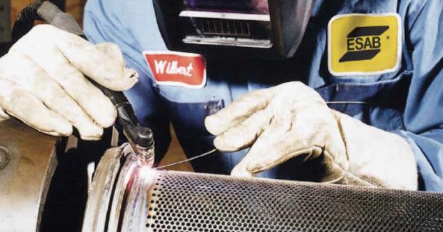
For highly repetitive welds, plasma welding increases reliability and repeatability and is frequently used as an alternative to gas tungsten arc welding. Here’s why.
Posted: February 3, 2016


The term plasma refers to a gas that has been sufficiently ionized to conduct an electrical current. As we see matter in the world around us, we are usually conscious of its existence in three states . . . solid, liquid and gas. We are all aware of the difference between solids, liquids, and gases, and the fact that increasing the temperature changes a material from one state to another. When enough energy is applied to a gas, this will cause an ionization of the gases atomic structure. This process is visible to us in the form of fluorescent lighting in our homes and offices, lightning in the night sky, or even our very sun. Most of the visible universe is a type of plasma.
When energy (heat) is added to a material in a gaseous state, the temperature of the gas keeps increasing. If enough energy s added, the temperature becomes high enough that the gas no longer exists as individual molecules. The molecules come apart and the material made up of individual atoms, if the temperature is further increased, the atoms will then lose electrons and become ions. This material then consists of a combination of ions (with a positive charge) and free electrons. Under these conditions, the matter now exists in a fourth state . . . the plasma state.
Plasma has many properties that are similar to those of a gas but also some special properties that make it unique. The most important property of the plasma, as far as welding is concerned, is that it contains free electrons which allows it to easily carry an electrical current. The plasma welding process does not have an exclusive on the use of plasma as it also exists in all other arc welding processes. Plasma welding utilizes the developed hot gases to provide unique benefits to the welding operation.
PLASMA ARC WELDING
Plasma arc welding (PAW) is a welding process that heats an inert gas to an extremely high temperature so that the gas becomes ionized and electrically conductive. This plasma gas is constricted into a column by an orifice placed downstream of the electrode which is
protected inside the nozzle of torch. The plasma is used to transfer an electric arc to the workpiece to obtain the melting and coalescence of most metals and to constrict the arc during the welding process.
Plasma welding is not a new process to the industry, but only in the past few years has it gained significant acceptance. Until recently, the process was considered exotic and difficult to understand. This was mainly due to the applications it was being adapted to. Plasma now has proven its value in the area of highly repetitive automated welds. The process provides increased reliability and repeatability to meet today’s high standards of productivity. It is frequently used as an alternate to the gas tungsten arc welding process (GTAW).
All metals amenable to GTAW or TIG welding can be welded with the plasma arc process. Plasma arc welding shows its greatest advantages in the welding of high volume repetitive production operations. These applications normally demand repeatable welds on a near continuous basis using the melt-in fusion mode and include spot fusion welds, corner edge welds, lamination welds and circumferential / seam welds. For most applications, the plasma arc process offers increased electrode life, reliable arc starting, improved arc stability,
better penetration control and reduced current levels. In some cases plasma offers increased travel speeds, improved weld quality, and less sensitivity to operating variables.
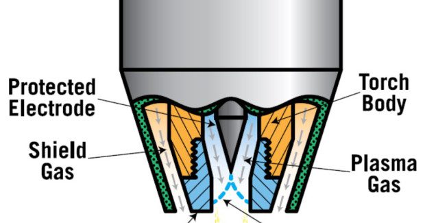
THE PROTECTED ELECTRODE
One of the most important features of the plasma arc welding process is the Protected Electrode which provides higher efficiency and reduces downtime in most applications. The tungsten electrode, which is secured inside the plasma torch and behind the orifice, is protected from outside impurities that would normally attack its hot surface. With this protection, the electrode is shielded from materials that can constantly attack an “exposed” electrode. The protected electrode in the plasma welding torch normally requires a change only once every eight hours for most operations. This reduction in electrode change allows for increased productivity.
The electrode is secured externally in the TIG welding process (GTAW). This exposes the electrode to the contaminants (stamping and forming oils, degreasers, oxides, etc.) present on the surface of the base material to be welded. These contaminants, under intense temperatures, will attack and erode the tungsten electrode requiring the frequent changing of the electrode on a repetitive basis.
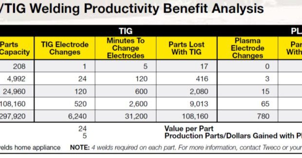
It is not uncommon in many applications for the electrode in the GTAW torch to require replacement changes one to two times per hour depending on part cleanliness and production levels. The time required to change the electrode depends on the accessibility of the torches on the fixture apparatus. Five minutes or more may be spent on each electrode change in some cases, eating away costly production time. Multiplying the number of electrode changes required in an 8-hour shift by the time required for each change, and dividing by the total amount of production time available, will yield the percentage of lost production time. Based on that number, it is now easy to figure parts lost due to frequent electrode changes. This reduction in electrode change allows for increased productivity.
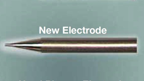
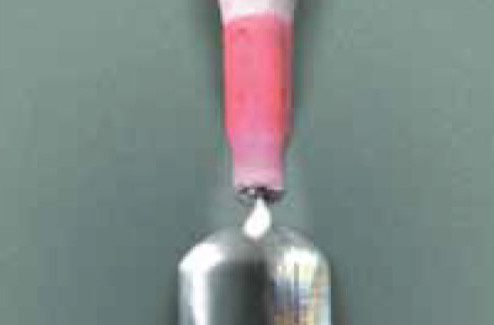
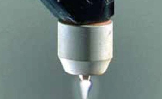
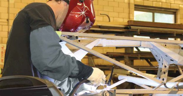
Simply stated, plasma arc welding is a superior variation to TIG welding (GTAW) that encloses the tungsten electrode in a protected environment (see Figure 1) and delivers the arc through a cooled copper tip. Enclosing the electrode protects it from contamination, thus substantially extending its life. The constant stable arc shape of plasma results in consistent welds for eight hours or more of operation, as compared to automated TIG welding, where deterioration of the exposed TIG electrode (see Figure 2) can result in weld arc variations (see Figure 3) in one hour or less of operation.
Plasma arc welding uses a pilot arc (see Figure 4) to consistently transfer the arc to the work without the repeated use of high frequency current.
PILOT ARC
Another outstanding feature of the plasma arc welding process is the pilot arc, which provides reliable arc starting and contributes to the repeatability and increased productivity of plasma welding. The pilot arc is a low current DC arc that is sustained in the tip area of the torch to ionize a gas as it passes around the electrode and through the orifice. Arc initiation is provided by the pilot arc that transfers between the tungsten electrode and the tip. It is started by imposing high frequency (from a small high frequency generator or C.D. arc starter inside the control console) on a low DC current for a short duration of time to ionize the gas.
Once the pilot arc has been established, the requirements for high frequency are no longer needed. The pilot arc now remains on to reliably assist the starting of the main transferred welding arc from a separate DC power source. Without the need for high frequency used in TIG welding (GTAW), the erosion of the electrode by constantly etching its surface is diminished. This eliminates the phenomena of inconsistent arc starting, resulting in the loss of arc directability. The use of a pilot arc instead of conventional high frequency circuitry provides extremely reliable arc starting. This repeatable arc initiation nearly eliminates significant downtime and minimizes the number of rejects or reworks due to poor welds, thus reducing scrap.
CONSTRICTED ARC
An orifice (also called a nozzle or a tip) which is inserted into the front end of the torch body provides for the laminar flow of the plasma gas and constriction of the arc. The magnitude of this constriction is normally controlled by three variables . . . the orifice diameter, the plasma gas flow rate, and the electrode setback (the distance the electrode is recessed within the tip). The arc will be most constricted when the torch is operated at higher plasma gas flow
rates and the electrode placed at maximum setback.
This type arc is typically used when trying to achieve keyhole single pass welds requiring maximum penetration, narrower weld beads, minimized heat affected zone, and reduced base material distortion. Keyhole welding is generally used on material thickness ranging from .090 in (2.3 mm) to .250 in (6.4 mm). By reducing the electrode setback and plasma gas flow rates, a softer, less constricted arc will occur. This type arc is typically used for the melt-in fusion (non-keyhole) mode and allows for faster travel speeds on reduced base material thickness .010 in (.3 mm) to .187 in (4.7 mm).
DETERMINE YOUR PLASMA ARC WELDING SYSTEM REQUIREMENTS
- Microplasma welding (typical current range 0.1 – 15A): Microplasma is used for welding thin sheets [down to 0.004 in (0.1 mm) thickness], and wire and mesh sections. The needle-like, stiff arc minimizes arc wander and distortion.
- Medium current welding in the Melt-in Fusion mode (typical current range from 15 – 200A): This is an alternative to conventional TIG. The advantages are deeper penetration (from higher plasma gas flow), greater tolerance to surface contamination including coatings (the electrode is within the body of the torch) and better tolerance to variations in electrode to workpiece distance, without significant change in heat input.
- Keyhole welding (typically over 100A): By increasing welding current and plasma gas flow, a very powerful plasma beam is created which can achieve full penetration in a material, as in laser or electron beam welding. During welding, a keyhole is formed which progressively cuts through the metal with the molten weld pool flowing behind to form the weld bead under surface tension forces. This process can be used to weld thicker materials [up to 3/8 in (10 mm) of stainless steel] in a single pass.
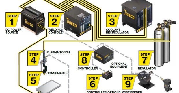
A typical plasma welding system consists of:
Welding Console
The pilot arc control console is the ‘mixing box’ into which the power, gases and coolant are controlled and monitored. It has a small DC power supply for the pilot arc. Some consoles provide additional controls and digital meters to assist in weld parameter control.
DC Power Supply with a Suitable Welding Range
A typical DC power supply with constant current characteristics, remote contactor/current control, and suitable welding range is recommended for most operations. A solid-state power supply with a non-mechanical contactor is recommended when performing high duty cycle short duration welds. Plasma arc welding is done almost exclusively with the use of straight
polarity (DCEN). The use of an AC Square-Wave power supply is recommended for the welding of aluminum or aluminum alloys.
Inert Gas Flow Gauge Regulators
Two flowgauge regulators for plasma and shield gases are required to control inert gas flow from cylinder tanks.
Plasma Welding Torch (Manual or Mechanized)
A plasma welding torch suitable for the particular welding operation should be used. Torches are available with various head and size configurations. All are liquid cooled. The orifices of some torches are also liquid cooled to provide improved orifice life and higher current carrying capacity. Plasma torches use tungsten electrodes, which are normally 2 percent
thoriated.
Closed Loop Coolant Recirculator
A coolant recirculator of a nonferrous design must be used. The use of deionized water to prevent electrolysis in the torch is required.
Optional Accessories
Options for the plasma welding system could include weld controllers with remote hand pendants and cables. A weld sequencer package would be needed to monitor and control pulse, weld timing, current and gas slopes. For applications using filler metals, a wire feeder capstan with spool assembly and torch bracket would be required. All products and
options are available from your local distributor.
MODE OF OPERATION: MELT-IN FUSION WELDING
Plasma welding is commonly used in two modes of operation, melt-in fusion welds and keyhole welds. Melt-in fusion welding is the most often used with the plasma arc welding process. It is accomplished with a softer, less constricted arc, using lower plasma gas flow rates, a reduced electrode setback, and current levels in the range of up to 200 amps. The minimum electrode setback distance is obtained with the electrode point set flush with the face of the tip.
Subscribe to learn the latest in manufacturing.

Industry News