Cutting Corners: The Idea Behind Power Ramping
Although power ramping has proven to be highly beneficial, it is often underutilized on the shop floor because fabricators either do not understand its benefits or they just don’t know how to use it. By simply applying the given values and principles presented here, they will see a visible improvement in corner and radii cut quality.
Posted: May 6, 2016
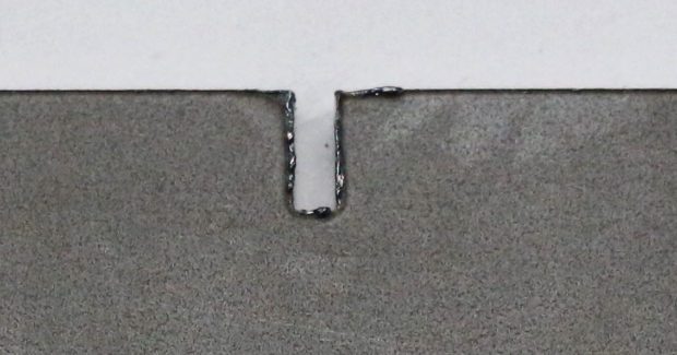

When it comes time to cut a sharp corner or radii in sheet metal with a 2D laser cutting machine, many shops experience the struggle of achieving perfect cut quality. Fabricators often end up with a finished part that has small burrs or striations in those specific areas and the issue becomes even more apparent as cutting feed rates increase. The poor cut quality is due to the machine changing feed rates so rapidly and in a relatively uncontrolled manner in order to cut corners accurately, while simultaneously applying too much power to the material.
One common solution to this issue is to process the part(s) with multiple contour sizes. In some cases it might even make sense to switch from large contour to a smaller contour just for cutting the corners. However, while this is not necessarily a bad idea, this approach can take a significant amount of time that will considerably reduce the overall cut times and productivity. So what is a better alternative?
WHAT IS POWER RAMPING?
By adjusting or ramping down the laser power just as the laser head approaches the corner, and ramping up the laser as it accelerates out of the curve, it is possible to minimize burrs and striations. This is known as power ramping, or Analog Power Control. The power ramping feature is typically meant to be used when cutting with air or nitrogen in thinner materials that are 3 mm (0.12 in) thick or less. The best applications are in thin to mid-range material when nitrogen is used as the assist gas to increase the edge quality when cutting large contours. The power ramping feature is not as beneficial when cutting with oxygen because of changes to the properties of the assist gas and the decreased feed rates that occur. Typically, lower speeds do not lead to the same issues with burr and striations since the laser has enough time to decelerate before reaching a corner.
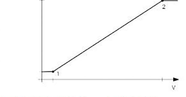
When the application is a good fit for power ramping, the operator simply turns the Power Ramping function on in the technology tables. This allows them to adjust the laser power and gating frequency when the motion unit is not cutting speed at full speed, as is the case when it is processing corners and radii. The process is represented by a linear transition between the two elements (see Figure 1).
HOW DO YOU USE IT?
When experiencing a bad cut, it can be difficult for the operator to tell whether the power ramping settings are the culprit or if the main technology tables simply need to be adjusted. The easiest way to save time and accurately diagnose the issue is to create a test program with the Adaptive Control OFF. The location of this option varies based on the laser system being used and the manufacturer of the control system.
With the TruLaser 1030 and 2030 series machines, for example, the option is referred to as “Adaptive Control” and can be found in the “Technology” tab. A page in the “Cutting” area is dedicated solely to those parameters. On TruLaser series 3001 and 5001 machines that feature a Siemens 840D control, the operator has the option to activate (1) or deactivate (0) Analog Value Control, and also does so from the “Technology” tab. For shops who use one of our CO2 laser cutting machines, SprintLas must be programmed in order to use power ramping. Check the NC code where the rule is represented by a TC_LASER_ON command. Once the settings are adjusted, the operator should run a test part and look for burrs or striations. If they are only within the corners and radii of the part, then the issue is related to power ramping.
DEFINING PARAMETERS
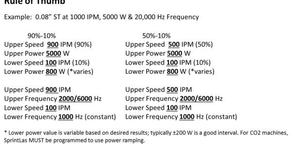
Once you have identified that power ramping is the cause of burrs and striations, how do you make it work for you instead? As a rule of thumb, the following parameters have been proven to work consistently:
Begin by adjusting large contour cutting speed to the highest speed possible when laser cutting a simple straight line. Record or remember this speed – you will need it later. Next, make sure power ramping is ON. As noted above, this can be done a couple ways, depending on the type of machine. Set the upper limit speed parameter to 90 percent of the given large contour speed, per material thickness. Then set the lower speed parameter to 10 percent of the given large contour speed. The upper laser power parameter should be the maximum laser power used for large contour. The lower laser power parameter should be set to about 800 ±200 Watts. This value can vary simply because too much laser power can cause dross, while too low of a power can actually lead to welding. The lower limit frequency parameter should be set at 1,000 Watts as a constant. Finally, the upper limit frequency should be either 2,000 Hz or 6,000 Hz.
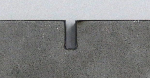
This method is referred to as the “90 percent/10 percent” rule. If further tweaking is needed, the upper and lower speed parameters can be split to create a more cautious “50 percent/50 percent” rule (see Figure 2). When you run the part with these parameters, you should see a marked improvement in the cut quality.
WRAP UP
Although power ramping has proven to be highly beneficial, it is often underutilized on the shop floor. Fabricators either do not understand its benefits or they just don’t know how to use it. By simply applying the given values and principles presented here, they will see a visible improvement in corner and radii cut quality. For those who may be concerned about how this method affects overall processing time: in most cases it is virtually a non-issue because the machine only slows down for a split second and only in certain areas of the part, meaning the overall increase in processing time is extremely minimal. Knowledge of power ramping can advance the production of a job shop with high variety parts or a product shop with a specialized niche – regardless of the laser type.
Subscribe to learn the latest in manufacturing.

Industry News