Approaching Removal Jobs from a New Angle
Efficient attachment removal has always been tricky. Without the ability to mechanically position the tool so that a closer cut can be achieved with less residual metal, workers were forced to deal with the drawbacks of traditional removal processes. But not anymore: A small alteration has made a huge impact on the attachment removal process.
Posted: May 22, 2017
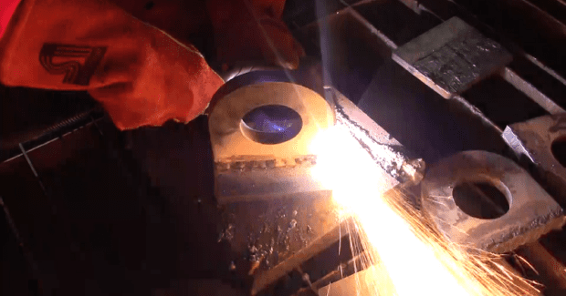


Efficient attachment (e.g. pad eyes, lugs, gussets, tabs, flanges, etc.) removal is a tricky task, but essential to the successful completion of metalworking projects. From large to small-scale projects, construction sites to workshops, the ability to produce a clean, flushed result requires the right tool and removal method. A pristine finish, after the removal of an attachment, often comes at the cost of additional labor and resources. Traditional methods of removal, such as plasma cutting, oxyfuel cutting, and carbon arc gouging (CAG), leave behind sizable metal remnants. Attempts to avoid this by cutting closer with traditional tools may result in scarring of the workpiece. The metal that remains must be meticulously ground away, resulting in additional labor costs and the risk of a workplace injury from the grinding wheel ergonomics and potential debris that are generated.
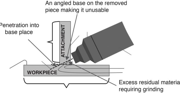
Without the ability to mechanically position the tool so that a closer cut can be achieved with less residual metal, workers were forced to deal with the drawbacks of traditional removal processes (see Figure 1).
MAKING MODIFICATIONS
With this lack of closer access in mind, our team of plasma process engineers realized that the answer required a modification to the tool that would allow the angle of the plasma arc to sit parallel to the workpiece. However, this seemingly simple solution presented a few technical hurdles. The first was how to redirect the arc. Normally in plasma cutting tools, a high velocity of air forces the plasma stream through the nozzle bore in a straight line. Changing the position of the nozzle bore would not itself influence the direction of the plasma stream. This would simply drive the plasma into the bore and shield, damaging both of them. The engineers found the key to guiding the plasma was in controlling the swirl of air around it. In doing so, they could successfully design a new path for the plasma arc.
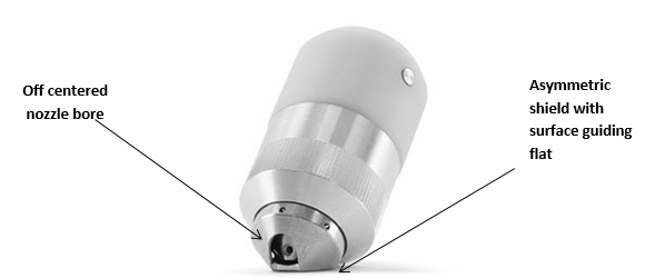
The second issue involved developing a bore that would allow this new arc to cut closer to the base material, but also maintain a desirable thickness for cutting. Our engineers methodically tested potential configurations. By developing a set of bore feature aspect ratios that could accommodate the flow of gas, they were able to create a plasma stream with enough arc density to compete with the thickness capabilities of cutting tools currently on the market. Lastly, the shape of the shield and nozzle had to be sculpted in such a way that was ergonomic and would allow the plasma stream to sit parallel to the base material. This was achieved with an asymmetric shield and nozzle interface. With one flat side angled to sit against the workpiece, the shield offers greater stability and control than its predecessors.
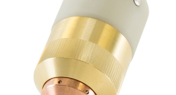
In consideration of ergonomic requirements, the engineers designed the nozzle and shield as a single interlocked piece where all parts would rotate in relation to each other. This design, known as FlushCut, provides flexibility to the user while maintaining proper alignment (see Figure 2).
CUTTING FROM A NEW ANGLE
After years of research and development, FlushCut consumables are now entering the market and enabling a flush cutting application that never existed before. As proposed, this new design offers an asymmetric shield with a surface guiding flat and an off-centered nozzle bore. Now able to minimize the cutting angle and the distance between the arc and the workpiece, the user can comfortably achieve a parallel cut, significantly reducing the residual material. The guiding flat increases stability and allows the user to easily drag the torch against the workpiece while achieving a straight, close cut.
TRADITION MEETS INNOVATION
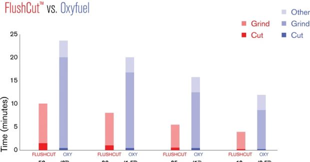
Not only does the flush cutting process serve as an improvement to current plasma cutting processes, it successfully competes against non-plasma methods as well. When tested against traditional cutting techniques, the Powermax® FlushCut process outperformed both CAG and oxyfuel in the amount of time spent completing an attachment removal job. Although the actual metal removal is quick, the primary drawback to CAG has been the amount of waste and labor it creates afterward. The process often causes scars in the workpiece that can require extensive, costly repairs. The CAG process may also dig into the attachment being removed rendering it unusable for future projects. By design, the FlushCut process avoids this extra repair cost by sitting flat against the workpiece and guiding the arc through the attachment at a much smaller angle. This reduces the overall process time from start to finish.
Like CAG, oxyfuel poses drawbacks that are costly and time-consuming. The intense heat involved in oxyfuel cutting creates a heat affected zone (HAZ) that could cause thermal damage to the workpiece. To prevent this, metalworkers must avoid cutting too close to the base and instead cut into the attachment at least ¼ in from the workpiece. With this loss of material, the attachment is usually not suitable for reuse. Left with extra metal, workers arduously grind away at the remnant, costing extra labor hours and increasing the risk of a work-related injury. When compared to CAG, the FlushCut process can produce a quicker and cleaner result than oxyfuel cutting due to the nature of its design. Although oxyfuel and the FlushCut process are nearly identical in the actual time it takes to cut through metal, it’s the reduced prep time and lack of residual material left over that sets FlushCut process apart.
Without the need to pre-heat and with the ability to cut much closer and require less grinding after the cut, the FlushCut process proves to be a much more efficient method for attachment removals than oxyfuel (see Figure 3).
IMPROVING EFFICIENCY
What might seem like a small alteration has made a huge impact on the attachment removal process. Metal workers familiar with standard cutting practices are finding the new asymmetrical shield and surface guiding flat increases efficiency and decreases time and resource waste by reducing grinding time. Without requiring extra labor, more projects can be completed within the same timeframe and with less risk to workers.
Subscribe to learn the latest in manufacturing.
Industry News