What You Must Know About Die Safety Blocks
They protect anyone working in the die area of a press from a free-falling upper die/slide if a brake or counterbalance fails, a pitman arm or adjusting screw breaks, or hydraulic pressure is suddenly lost. These devices look simple, but many shops struggle with what type of to use, how many to use, and where to put them. Here’s what you need to know.
Posted: May 31, 2017


Die safety blocks are called by many names: safety blocks, ram blocks, die blocks or prop blocks. Regardless of their description, die safety blocks all have the same purpose: provide protection to anyone working in the die area from a free-falling upper die/slide. This all-too-common accident happens in the event of a brake or counterbalance failure, broken pitman or adjusting screw, or a sudden loss of hydraulic pressure on presses. While die safety blocks are simple devices on the surface, there are many factors to consider in choosing what type of to use, as well as how many to use or where to put them. As a result, many shops struggle with this topic.
OSHA REGULATIONS
Die safety blocks are required by OSHA CFR 29, Subpart O, 1910.217 (d)(9)(iv) Mechanical Power Presses, which states, “The employer shall provide and enforce the use of safety blocks for use whenever dies are being adjusted or repaired in the press.” While OSHA does not require the use of safety blocks during die setting, safety-focused shops include them during die setting procedures as a best safety practice. Proper use of die safety blocks also satisfies federal lockout/tagout requirements for controlling mechanical energy. It is important to be aware that multiple ANSI B11 safety standards require the use of electrical interlocks with safety blocks since they are only designed to hold the static weight of the slide and upper die, not the driving force of the press itself.
Any time an employee needs to put their hands in the die area of a press or is required to work on the die, they must follow OSHA regulations without exception. At no time should the employee make any adjustments or service within the die space area without taking proper protection measures that meet OSHA and ANSI requirements. Regardless of how time-consuming the process, the company is legally responsible – and liable – for using these procedures in a press shop. According to ANSI B11.19-2003, safety blocks “shall be interlocked with the machine to prevent actuation of hazardous motion of the machine.” The following interlock systems will satisfy this requirement. The electrical interlock system for die safety blocks must be interfaced into the control system so that when the plug is pulled, the power to the main drive motor and control is disconnected. If the machine has a mechanical energy source, such as a flywheel, it must come to rest before the die block can be inserted.
In recent years, the rate of non-fatal injuries for press operators has significantly dropped, indicating that safeguarding equipment and effective regulations are preventing common injuries. However, a careless press operator can still cause great harm to himself or to others by neglecting to follow proper die safety block procedures.
INSTALLATION TIPS
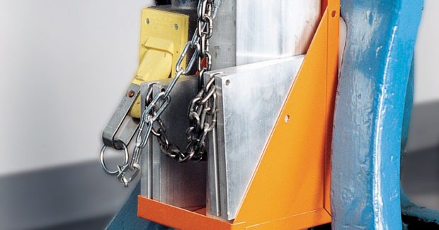
With the press motor off and the flywheel at rest for mechanical presses, safety blocks are placed between the die punch and holder while the machine stroke is up. The number of safety blocks is determined by the size of the press bed and the weight the blocks must support. On larger presses, the total slide weight must then be distributed among the quantity of safety blocks required. As many as four safety blocks may be needed in larger scale applications. Rams are usually adjustable, so wedges or the adjustable screw device is offered to provide a proper fit. If the die takes up most of the space on the die set, it may be difficult to find a place to insert the block. To avoid accidentally stroking the press or leaving the safety block in the die after use, an electrical power cut-off interlock system should be used.
Again, note that electrical interlocking of die safety blocks to the machine’s motor and control circuits is required by ANSI B11.19. This critical step breaks the electrical circuit to the main motor and feed drive so that it cannot run when the safety blocks are put in the die area.
DIE SAFETY BLOCK CALCULATIONS
Three factors need to be determined to guide the selection of safety blocks: static load, block length and block size.
(1) Determine Static Load
The actual static load that the die safety block will support is determined by adding the actual weights of the press slide and slide components, such as the ram-adjustment assembly, connection rods or pitman arms, and the upper die. If this weight cannot be determined, an approximate static load can be calculated using the formula below. Allow 2,000 lb of static load for each cubic foot displaced in the press bed area (front to back x right to left) multiplied by the shut height (die space) of the press. Note: When using this formula, the calculated approximated static load has a safety factor of two.
Static Load Formula
- [Press Bed Area (sq in) x Shut Height (in)] / [Cubic Inches/Cubic Feet (1,728 cu in/cu ft constant)]
- Cubic feet displaced x 2,000 lb/cu ft = Total Static Load
Example:
- Press Bed Area = 48 in x 96 in
- Shut Height = 24 in
- (48 x 96 x 24) / 1,728 or 110,592 / 1728 = 64 cu ft
- 64 cu ft displaced x 2,000 lb/cu ft = 128,000 Total Cubic Static Load
(2) Determine Block Length
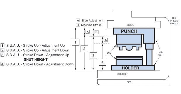
With the machine at the top of its stroke, stroke up – adjustment up (S.U.A.U.), measure the space between the upper and lower die set plates, and not the distance between the bolster and slide. This gives the maximum safety block length. To determine the S.U.A.D. measurement, subtract the ram adjustment from the S.U.A.U. figure. This provides the minimum length of the die safety block.
Exceptions:
- If wedges will be used, subtract 1-1/2 in maximum. This is an allowance for variation in the stopping point of the crankshaft or adjustment of the ram.
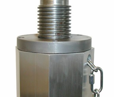
- When an adjustable screw device is added to an octagonal safety block and the screw is all the way inside of the safety block, it will add 2 in to the overall length of small and medium safety blocks and 2-1/2 in to the overall length of large safety blocks. Therefore, subtract 2 in for small or medium blocks and 2-1/2 in for large blocks to determine the length of the aluminum portion of the die block.
For example, if the minimum overall length of the small or medium safety block required is 10-1/2 in with any size adjustable screw device, the aluminum portion of the safety block would be 8-1/2 in (10-1/2 in – 2 in = 8-1/2 in). Or if the minimum overall length of the large safety block required is 16 in with any size adjustable screw device, the aluminum portion of the safety block would be 13-1/2 in (16 in – 2-1/2 in = 13-1/2 in).
(3) Determine Block Size
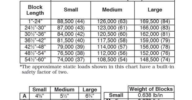
The size of the die safety block – small, medium, large – is determined by one or both of the following factors:
- The size of the block itself and the area available in the die.
- The static load capacity of the block versus the total static load being supported.
To further customize their unique solutions, die press operators can also choose wedge shapes for their safety dies, such as X, U or octagon shapes, and to meet any size requirement.
Subscribe to learn the latest in manufacturing.

Industry News