Do Your Toolholders Fit Your CNC Spindles?
Here are some reasons why your toolholder may be showing finish wear at the threaded area and at the gage line, how to inspect where the threads have expanded the toolholder, and how to prevent all of this from occurring.
Posted: October 5, 2009

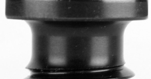
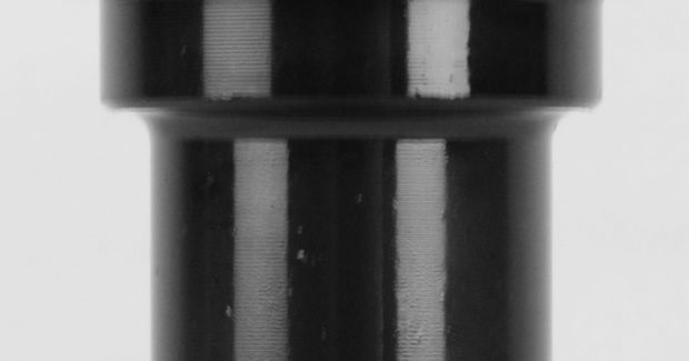
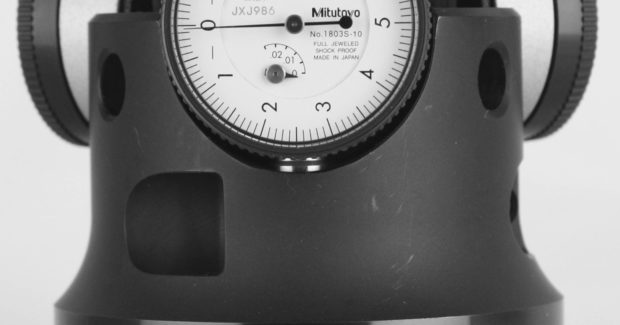


Why is your toolholder showing finish wear at the threaded area and at the gage line? We’ve been asking this question for some time now, and we know the answer. The marks at the gauge line (large end) of the taper shank are normally ¼ in to ½ in long and look as if the holders were fretted, displaying an unusual wear pattern. The marks at the small end are where the threads have expanded the toolholder.
We examined measuring instruments that are currently available in the marketplace and determined that there really wasn’t an inexpensive method for measuring taper shank diameter changes. This led to the design and build of our prototype of the Taper Shank Test Fixture (patent pending). This prototype gauge measures the distance the test fixture moves away from the tool flange, detecting growth in diameter of the toolholder to as little as .000003 in.
We purchased three toolholders and three retention knobs of some popular brands and inspected and compared them to the national standards. We then developed test protocol. First, prior to installation of the retention knob, the test fixture was positioned on the toolholder shank and all three indicators resting on the flange of the toolholder were adjusted to “0”. Second, the test fixture was removed and the retention knob installed to a predetermined torque value. Third, the test fixture was reinstalled, and the average movement of the three test indicators was recorded.
We removed the test fixture and the retention knob from the toolholder. The test fixture was reinstalled on the toolholder without a retention knob and the three test indicators were checked to make sure they were still set on “0”. This insured that the indicator’s readings were correct and they were not moved during the testing of the toolholder. We started the tests at 20 ft-lb of torque with retention knobs lubricated with light oil. Three retention knobs of the same manufacturer brand were checked in a row, and all of the toolholders were checked in the same order with each retention knob initially.
In subsequent tests, we checked two from each manufacturer. We used torque values from 20 ft-lb up to 160 ft-lb during our initial testing; new tests of the retention knobs were checked at torque values of 20 ft-lb through 80 ft-lb.
We have now moved into the second generation of the Taper Shank Test Fixture. We contracted with a company that specializes in rebuilding and regrinding spindles to have this new hardened fixture ground. This fixture actually mirrors the toolholder taper, detecting any increase in size over basic, no matter how small the increase or where the distortion occurs along the length of the toolholder. This is significant in that most toolholder manufacturers use air gages to check the rate of taper at three points of the holder, but not the full length of the taper.
Our fixture actually takes an out-of-round condition into account, unlike the air gage. Our inspection and testing showed that a toolholder, when checked with an air gage, indicated one AT3 grind limit out of tolerance. Checked again with the Taper Shank Test Fixture, the same toolholder was three AT3 grind limits out. Also, our fixture self-compensates as it will not show expansion or growth in size until the toolholder expands or deviates enough to register as movement above the grind limit.
Keep in mind that toolholder tapers are ground to a total tolerance of .000080 inch in a Class 3 fit (AT3). Growth at the small end of the toolholder results in a poor fit in the large end of the toolholder with the spindle. This in turn results in erratic positioning of the toolholder when loaded into the spindle and inconsistent concentricity at the tool tip. Our testing with both generations of the test fixture proved that toolholders should be checked for expansion prior to their installation in the machines. The test results revealed that retention knobs started to expand the shanks of the toolholders at a much lower torque value, as low as 5 to 15 ft/lb, and that without exception, all toolholders return to their original size after removal of the retention knobs.
Test Conclusions for the Small End of Toolholders
- In analyzing test data, it is clear that the burnishing is caused by an expansion of the small end of the toolholder from the pressure of the threads of the retention knobs.
- The torque used in industry to tighten retention knobs expands the tool shank far beyond the grind limits used by tool manufacturers. In some cases the expansion is up to 40 times the grind tolerance.
- The torque value used to tighten the retention knobs with no expansion of the toolholder shank (less than 30 ft-lb), is too low to be considered adequate by most workers.
- Thread finishes had a great deal to do with holder expansion. Parts with better thread finish caused less holder expansion.
- Thread rolled retention knobs were less acceptable than parts with cut threads.
- Some retention knobs were not hardened to the specifications spelled out in the five international standards and were not case hardened.
NEW HIGH TORQUE RETENTION KNOB DESIGN
Using the first generation of our test fixture, we began experimenting with the actual retention knob design. Using that fixture, we found that standard retention knobs inserted into the toolholder with as little as 20 ft-lb of torque expanded the toolholder shank. Using the newest design of the test fixture, we now know that the toolholder actually will begin to expand with as little as 5 ft-lb to 15 ft-lb of torque. Even in light of these new findings, we have proven that the new, High Torque retention knobs, when tightened to the same torque value as standard retention knobs, expand the toolholder shank two or three times less than standard knobs.
The inclusion of a pilot on the high torque ANSI retention knobs greatly reduces the likelihood of retention knob breakage, especially when the Belleville washers are not performing at full strength. The High Torque retention knobs are designed to be balanced dynamically from end to end, which makes it much easier to keep balanced toolholders within tight balancing tolerances after installation.
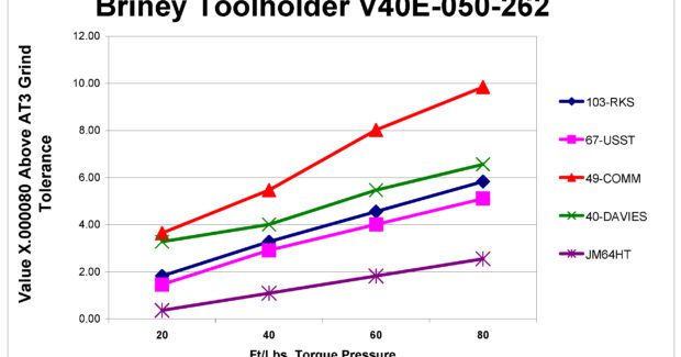
The nearby graph indicates the growth we experienced while testing using the second generation fixture and the High Torque retention knobs compared to standard retention knobs. The vertical axis on the graph is based on a toolholder grind tolerance of 0.000080 in. The greatest deformation reflected by the graph, at 80 ft-lb, is approximately ten times the tolerance, or 0.0008 in. While this number may seem miniscule, bear in mind that this discrepancy increases by a factor of 3.40 in or 0.0027 in. This number represents the distance that the toolholder moves out of the spindle due to the deformation of the toolholder. The resultant impact is that a toolholder that measures 5.400 in long from the face of the spindle to the tool tip may run out up to 0.002400 in TIR.
Test Conclusions for the Area at the Gauge Line
- When CNC machine toolholders are changed, the holders stop short of seating properly in the spindle. This distance is from .0001 in to as much as .002 in.
- When using end mills or slab mills, pressure from the cutting force moves the toolholder causing them to rub on the side of the spindle, 180 deg from the cutting direction. This has the effect of fretting a second angle at the gauge line of the toolholder.
- Tool run-out causes uneven chip load and reduces tool life, feed rates must be reduced to hold finish and tolerances.
- Run-out and vibration, break the fine razor edge on carbide tools prematurely.
- High speed tools are balanced before retention knobs are installed. The toolholder after the retention knob is installed will not seat in the same exact position every time the CNC changes tools. This contributes to tool life variance from one tool to another in the same cutting operation.
The same graph illustrates that the same toolholder, paired with a High Torque retention knob, may experience tool tip run out up to 0.000576 in TIR, which is a significant difference. Simply stated, the two numbers represent the diameter the tool would be free to move forward and back or side-to-side. Therefore, by implementing lower torque pressure during retention knob installation, along with the selection of the best quality toolholder and use of a High Torque retention knob instead of a standard knob, the distortion problem is solved.
It’s important to maintain retention knob installation torque at an acceptable level. Machines with 40 taper spindles normally have draw bar pressure of 2,500 lb or less. Axial force of 1.25 times the draw bar force, or 28 ft-lb to 33 ft-lb of torque, is adequate to ensure that the retention knob does not lose contact with the face of the toolholder.
TOOL STUDIES
A titanium slab mill located in Georgia routinely made two or three tool tip changes per day using standard retention knobs. After installation of the High Torque retention knob, the same machine running the same job used only one edge of the tool insert with no tool tip change for five days. They realized an immediate savings of $448: standard knob tool cost = $480/5 days; high torque knob cost = $32/5 days. The same slab mill also runs aluminum at high speed. They reported that the tools run much quieter with the High Torque retention knobs. Because the tools fit the spindle better, the machine no long emits the high-pitched whine that often accompanies aluminum milling.
One Ohio user stated that their carbide porting tools are holding better sizes and tolerances and are not chattering. They have fewer complaints about tool edge breakage since converting from the standard knobs to the High Torque design. Another user in Ohio mills aluminum forgings, making high-end wheels for sports cars. They use a 1 in ball mill which extends 18 in from the face of the spindle. They previously experienced trouble with chatter and tool breakage. After switching out tools and installing the High Torque knobs, they reported that the new tools ran for over two weeks and the chatter and premature breakage issues have been resolved.
Note: Test documentation on this subject is available for download at www.retentionknobtorquetest.com.
Subscribe to learn the latest in manufacturing.

Industry News