USING 1 PERCENT NICKEL ELECTRODES FOR HIGHLY RESTRAINED WELDS, HIGHLY HARDENABLE STEELS
Circumstances exist in which the selection of low-hydrogen, mild steel electrodes such as ER70S-6 solid wire or E7018 stick electrode is not enough to prevent weld cracking. Regis Geisler of Lincoln Electric explores the reasons for this and offer possible alternatives to these filler materials.
Posted: August 2, 2011


“Lowering the ‘martensite start temperature’ of the weld metal counteracts the residual stresses developed during the welding process and removes one of the contributing factors related to underbead cracking.”


Circumstances exist in which the selection of low-hydrogen, mild steel electrodes such as ER70S-6 solid wire or E7018 stick electrode is not enough to prevent weld cracking. Here we explore the reasons for this and offer possible alternatives to these filler materials.
Several of my colleagues who have written welding columns have been consistent in their advice for the welding highly of restrained joints or the welding of highly hardenable steels such as AR400. For such applications they have unanimously and correctly recommended appropriate preheat to slow down the cooling rate of the weld.
They have also recommended utilizing weld deposits consisting of low-hydrogen, mild steel electrodes such as ER70S-6 solid wire or E7018 stick electrode. While in many situations this may be sound advice, a few fabricators have described to me the circumstances in which this electrode selection was not enough to prevent weld cracking. I will now explore the reasons for this and offer possible alternatives to these filler materials.
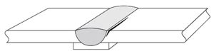
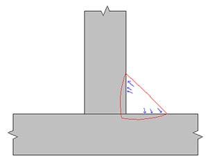
It must first be said that no one, including myself, will disagree with the use of adequate preheat and interpass temperature control (for either 1045 steel or AR400 plate, say 300 deg F) to slow down the cooling rate of the weld and the heat affected zone (HAZ) of the base material. Likewise, a low-hydrogen process is essential to prevent the migration of hydrogen (present in the electrode or the surface of the base material in the form of moisture) from the weld metal to the HAZ. This can result in underbead cracking when the base material has a susceptible microstructure. The concept of underbead cracking is depicted in Figure 1.
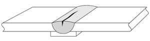
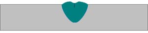
This means the selection of either ER70S-6 or E7018 electrodes is logical because these two consumables are inherently low in hydrogen. Solidifying that logic is the fact that these two types of weld deposits offer levels of ductility that are quite high, which can also help reduce the chances for weld cracking. However, sometimes even these normally sound precautions are not enough to prevent cracking – whether it is in the form of under-bead HAZ cracking or weld centerline cracking (centerline cracking is shown in Figure 2).
Now let’s consider why this can happen. According to one particular steel producer, the base metal chemistry of their version of abrasion resistant AR400 plate consists of approximately 0.30 percent carbon, 0.48 percent manganese, 0.25 percent silicon, 0.20 percent molybdenum, 0.88 percent chromium, .04 percent sulfur and .04 percent phosphorous.
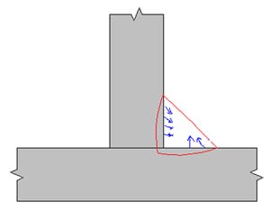
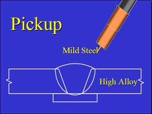
When constructing a T-joint consisting of two pieces of this steel, the fillet weld can wind up containing at least 0.15 percent carbon and 0.44 percent chromium when the above-mentioned low carbon filler materials ER70S-6 or E7018 are used. This makes sense, because for a fillet weld the pickup (the amount of the weld actually contributed by the base material) can be upwards of 50 percent or more. The concept of base metal pickup is explained pictorially in Figure 3.
This combination of weld metal and base material essentially creates a weld that is roughly equivalent to a 4118 steel having a relatively low level of de-oxidizers – specifically manganese and silicon. This grade of steel can have an as-cast tensile strength in excess of 100,000 psi, resulting from the elevated alloy content of the weld metal in conjunction with a fairly high cooling rate. This is a recipe for a weld possessing a microstructure that could contain a significant amount of brittle martensite.
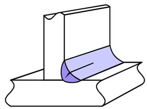
Making matters worse, the weld is susceptible to hot-cracking upon solidification due to the relatively low level of de-oxidizers. These de-oxidizing elements offer an innate resistance to hot-cracking by forming a matrix with low melting point elements (such as carbon) that have been swept to the middle of the weld bead. This hot-cracking phenomenon tends to be especially prevalent when the bead shape is concave as in Figure 4.
And as if that wasn’t enough to consider, the risk for underbead cracking in the HAZ can still persist even when precautions are taken. Granted, we have attempted to address the high hardenability of the HAZ of the AR400 plate by utilizing preheat and interpass temperature control and low hydrogen electrodes. However, because of the susceptible microstructure of the base material and a low critical hydrogen “threshold value” of the AR400 base plate, the residual stresses resulting from welding can still lead to underbead cracking problems. A drawing displaying these residual stresses acting in tension on the weld interface is shown in the Figure 5.
But what if there was a way to counteract the residual stresses developed during the welding process? We would then be able to remove one of the contributing factors related to underbead cracking. Interestingly enough, there have been scholarly studies conducted recently that have successfully done just that. Those efforts have been focused on lowering the “martensite start temperature” (Ms) of the weld metal.
This, described in one sentence, is the temperature at which austenite begins to transform into martensite. If the Ms is reduced to a low enough level, the welding residual stresses acting in tension on the base material can actually become compressive forces. In layman’s terms, this means that the weld no longer wants to pull away from the base material due to contraction stresses. Rather, at the interface, the weld metal tends to push against the base plate in a manner shown in Figure 6.
Just exactly how can the Ms be reduced? According to one of these studies1, the addition of nickel to the weld metal serves to reduce the Ms. So, through the use of a 1 percent nickel filler material such as SuperArc® LA-75, Excalibur® 8018-C3 or UltraCore® 81Ni1-A75, we can reduce the residual stresses in the weld. This, in turn, reduces the chances for underbead cracking. I have heard personal accounts of success when welding AR400 and other highly hardenable steels with 1 percent nickel-bearing electrodes, and I have recommended its use in applications similar to this for years. Now we have the science to back it up.
Yet another example of where 1 percent nickel electrodes have been shown to provide added benefits over ER70S-6 electrodes is in the single-pass welding of a one-sided single-V groove weld. Consider the case in which two ¼ in thick 1045 steel plates are to be joined, where the sidewalls of the plate have been beveled with a 45 deg included angle and a feather edge for a land. The plates have a 1/16 in root opening and a backing bar was used. A fabricator joining these two plates together had been using an ER70S-6 filler material and the spray MIG process.
This fabricator witnessed that the top surface of the weld bead generally exhibited what can be described as a “popsicle” shape as shown in Figure 7. The most likely reason for this unique bead shape was the force of the arc plasma generated by the relatively high amperage and voltage procedures used in an attempt to weld the part in one pass.
The forceful arc plasma caused the weld metal to flow down through the center of the puddle, and then circulate back to the top along the sides of the joint. The end result is that the weld metal tended to deposit more towards the edges of the weld on the top surface of the weld bead. Because of this, the center of the weld appears to be more depressed than the edges of the weld.
This bead shape, in effect, is concave in the middle of the weld. As mentioned earlier, this type of bead shape lends itself very readily to cracking. Also, because the two plates were highly restrained and unable to “wing” upward, the weld contained a high level of residual stresses. These factors, along with the segregation of low melting point elements in the center of the weld bead, caused the customer to frequently encounter centerline cracking in the weld.
Through the use of SuperArc® LA-75 and a pulsed MIG output waveform, the popsicle contour of the top surface of the weld bead was eliminated. Now, the top surface of the weld bead showed a convex shape, as shown in Figure 8.
This convex bead shape is a direct result of the more “sluggish” nature of the weld puddle because of the added nickel. Thanks to this – as well as the lower level of residual stresses provided by the SuperArc® LA-75 deposit – the negative effects of carbon and other low-melting-point tramp elements that have been swept to the middle of the weld were now less likely to cause centerline cracking. Needless to say, the fabricator was quite happy after switching to SuperArc® LA-75.
Time and again, welders and fabricators have realized the benefits of enhanced crack resistance when making welds with 1 percent nickel deposits provided by SuperArc® LA-75, Excalibur® 8018-C3 or UltraCore® 81Ni1-A75. Although there are some applications where electrodes containing 1 percent nickel are not appropriate (such as in H2S sour gas service pipe welds), consider using 1 percent nickel electrodes for highly restrained welds or highly hardenable steels.
1Çam, G. et al. (2010). “Progress in Low Transformation Temperature (LTT) Filler Wires: Review.” 63rd Annual Assembly & International Conference of the International Institute of Welding, 11-17 July 2010, Istanbul, Turkey.
Subscribe to learn the latest in manufacturing.

Industry News