How to Determine the Diffusible Hydrogen of Mild Steel Weld Filler Material
To avoid hydrogen-induced cracking, the hydrogen level in the welding filler material must be restricted to a certain maximum level. What exactly is the method for measuring the hydrogen content of a carbon steel weld filler material?
Posted: September 8, 2012


From the outset of my career I was taught the virtues of using an electrode capable of producing low hydrogen deposit. During my training the terms “cold cracking” and “hydrogen-induced cracking” were frequently conveyed as something to be wary of when welding of high-strength, low-alloy steels. Only recently have I given much thought as to how an electrode is actually determined to provide a low-hydrogen deposit. But in my current role, it’s become critical for me to take a keen interest. So what exactly is the method for measuring the hydrogen content of a carbon steel weld filler material? I’ll share some of the highlights of this process and offer some perspective.
It’s fairly well known that in order to avoid hydrogen-induced cracking, the hydrogen level in the welding filler material must be restricted to a certain maximum level. Hydrogen-induced cracking, which is better known to some as underbead cracking, is characterized by separation of the weld from the base material in the heat affected zone immediately adjacent to the weld metal. This phenomenon occurs within a few hours after welding has been completed and is partially a result of the diffusion of hydrogen from the weld metal into the base material. But migration of hydrogen to the heat-affected zone is not the only factor leading to this type of cracking.
While there does exist a certain threshold value for weld metal hydrogen content leading to underbead cracking, it is very much situation-specific. In addition to diffusible hydrogen content, underbead cracking is dependent upon base metal microstructure susceptibility, weld joint restraint, and welding residual stresses. Microstructure susceptibility to hydrogen-induced cracking most often increases with increasing steel base material strength. This means that for higher strength steels the use of electrodes with lower levels of hydrogen is important. But to apply the qualitative statement “use low hydrogen electrodes” is not sufficient because what is low for some steels may not be low enough for others.
While the effects on the base material due to weld metal diffusible hydrogen in welding operations (such as structural steel fabrication) can be significant, the effect of hydrogen on the weld metal itself is usually far less dramatic. In the course of filler metal qualification testing, the effect of excess levels of hydrogen may be observed during tensile testing. However, those effects are generally limited to a reduction in the ductility of the weld metal but have almost no appreciable effect on its tensile strength, yield strength, or toughness.
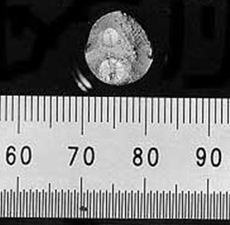
Occasionally a tell-tale sign of a high level of diffusible hydrogen content in the weld metal will present itself when a broken tensile specimen exhibits “fisheyes” on the fracture surface, as seen in Figure 1. Otherwise, it may not be readily determined from mechanical or impact testing that a weld metal has relatively high diffusible hydrogen. After all, an E6010 electrode that has been shown to have inherently high hydrogen content regularly provides in weld metal conformance tests CVN impact toughness results of 20 ft-lb or greater at a test temperature of minus 20 deg F.
For these reasons engineers and fabricators (are encouraged to) use specific statements in contract documents such as “only electrodes or electrode-flux combinations capable of depositing weld metal with a maximum diffusible hydrogen content of 4 ml/100 g (H4) are permitted to be used”, rather than general statements such as “use low hydrogen electrodes”. In order to accomplish this more accurate characterization of hydrogen content, the American Welding Society (Miami, FL) has set forth a weld metal diffusible hydrogen test method in AWS A4.3 “Standard Methods for Determination of the Diffusible Hydrogen Content of Martensitic, Bainitic, and Ferritic Steel Weld Metal Produced by Arc Welding.”
A diffusible hydrogen test is comprised of a set of four welded specimens, and all specimens must be welded within one hour from start to finish. The test pieces are about 1 in wide, ½ in thick and just over 3 in long. The fixture in which the specimens are restrained from moving is made of highly conductive copper and is cooled via water circulation. The copper fixture is to be kept cool, but not so cool as to cause condensation to occur on the surface of the fixture. Before any welding can commence, the test pieces must be heat-treated at a temperature greater than 750 deg F (usually at 1,150 deg F) for a couple hours in order to remove any hydrogen contained within them. Mill scale, which often has a black, flaky appearance, must be removed from the surface of the “blanks”; otherwise, the welded specimen could become contaminated and the hydrogen level of the weld metal unintentionally increased. Most often this task of removing mill scale is accomplished through the use of sandblasting. Further, in regards to sample preparation, the edges of the samples should be blunted to reduce the likelihood of a laceration injury to anyone handling the samples.
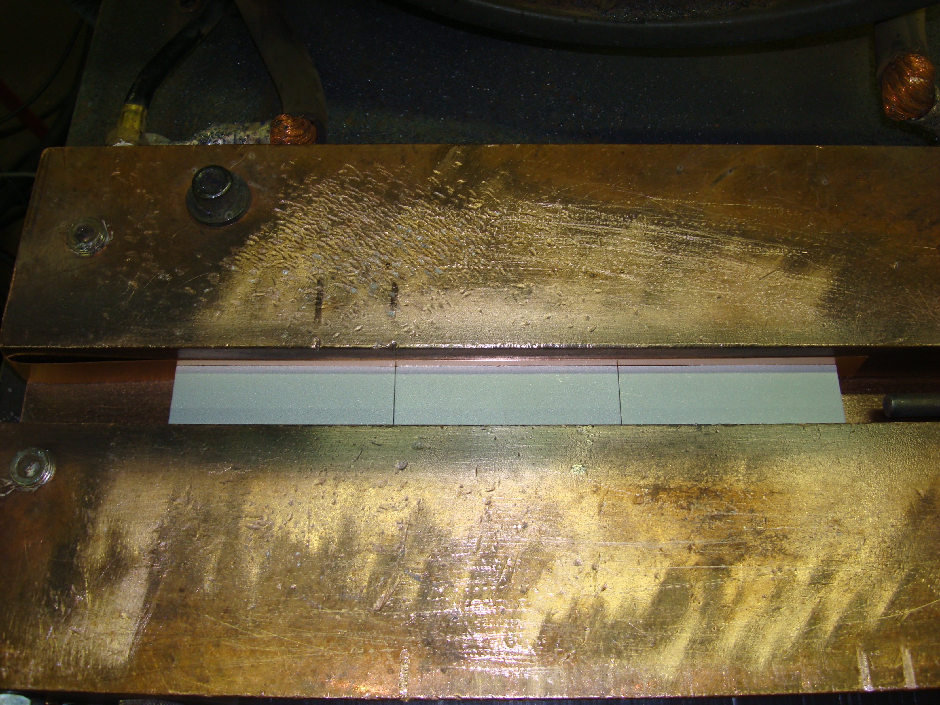
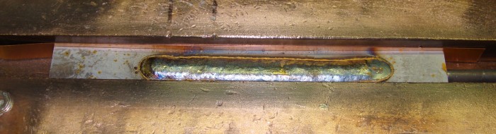
When handling the samples, the operator must take care not to introduce any oils from his or her skin to the surface of the steel, so clean gloves must be used when moving the plates into and out of the test fixture. Due to the fact that the blanks will re-rust very quickly after they are prepared, it is preferred that welding should occur on the same day. If, for whatever reason, hydrogen testing does not occur on the same day as sample preparation, the blanks should be stored with desiccant. Three blanks, which can be of equal size, are used as the test assembly and are aligned end to end as shown in Figures 2 and 3. It is important that there is no gap between the test pieces. Even a slight opening could cause air aspirate from the underside of the blanks into the weld puddle, leading to visible surface porosity. Worse yet, the situation could arise where there is no sign of visible porosity, but yet the hydrogen results could be skewed higher.
The blank in the middle is the actual test specimen from which the hydrogen content will be measured, while the two pieces on either end may be likened by some as the “run-on” and “run-off” tabs. These tabs can be the same length as the weld specimen, but in some high amperage welding processes, such as submerged arc welding (SAW), the run-off tab must be lengthened so that when the arc is extinguished the very tail end of the crater ends up on the run-off tab and not on the specimen (middle piece). Another consideration in diffusible hydrogen testing is the environment in which the welding is to occur. To ensure consistency across all diffusible hydrogen testing, the ambient air is to be maintained at 70 deg F and 10 percent relative humidity (10 grains of moisture per lb of dry air). If the temperature and humidity at which welding occurs is higher, then it is quite possible that the weld will absorb additional hydrogen. This would make an apples-to-apples comparison of testing results next to impossible.
Another facet to diffusible hydrogen testing is that automated travel carriages are typically used whenever possible. An automated travel carriage is particularly helpful for gas-shielded welding processes, as a consistent torch angle keeps the gas flow consistent and eliminates the weld puddle shielding variability that can occur when welding by hand. Further, hard automation lends itself to consistent contact-tip-to-work distance (CTWD). As I’ve discussed before, when the CTWD becomes shorter, the amperage increases to maintain a constant arc voltage. By keeping the CTWD steady the welding output amperage stays consistent. An instance where this is critical is when welding with gas-shielded flux core wire, as constant output amperage means that moisture contained within the electrode is evaporated at a constant rate. This also reduces the variability in weld metal diffusible hydrogen results.
It was mentioned above that the copper fixture is kept cool through water-circulation. Ordinarily in most welding applications, a certain minimum level of preheat would be desirable in order to promote the diffusion of hydrogen out of the weld metal. But in the case of diffusible hydrogen testing, the opposite is true. Here we want to cool the base metal and weld at a relatively fast rate in order to capture as much of the diffusible hydrogen as possible. Temperature control is essential, because hydrogen diffusion increases greatly with the temperature of the base plate.
Although a function of many variables, general hydrogen diffusion rates have been approximated. At 220 deg F, hydrogen diffuses through mild steel weld metal at the rate of one inch in approximately 48 hours. However, at 450 deg F, the diffusion rate increases exponentially, as hydrogen diffuses a distance of approximately one inch per hour. So, if the base weld and base metal remain warm for a longer period of time, it becomes much easier for diffusible hydrogen to escape. Again, a fast rate of diffusion of hydrogen is desirable in most circumstances, but it’s not so desirable when we’re trying to rate the level of hydrogen present in the welding filler material.
All welding procedures should be the same as those used during welding of the conformance test fixture from which tensile and perhaps other test specimens were removed. The only welding variable that may change is the welding technique. Weaving is not permitted under AWS A4.3, so in essence the only parameter that is allowed to differ is the travel speed. The requirement of using stringers only is intuitive, as slowing down the travel speed increases the temperature of the specimen, which as mentioned above can cause hydrogen to escape the weld pool more quickly. This is significant, as a reduction in travel speed can keep the specimen hotter for a longer period of time, skewing the hydrogen content downward.
As an aside, another example of the effect of a slower travel speed becomes apparent when testing the combination of wire and flux submerged arc welding consumables. A slower travel speed in the SAW process can lead to more flux being consumed by the welding arc, which has the potential of increasing the hydrogen content of the weld metal. Once welding is complete, the specimens should be removed with a pair of vice grips, and immediately dipped into an ice water quench bath. After the specimens have been quenched in ice water and vigorously stirred within for 20 sec, they are then transferred to a holding container with a liquid bath at a temperature less than minus 76 deg F. For illustration, this can be accomplished with a Dewar filled with methanol and cooled with dry ice. A layer of dry ice several inches thick in the bottom of the Dewar should be sufficient. It is imperative that the welded specimens be transferred to this liquid holding tank within 60 sec after the arc is extinguished.
After having been in the liquid bath for at least two minutes, the specimens may be taken out for the purpose of processing the welded specimen. Breaking off of the run-on/run-off tabs and removing any slag, smut, or silicon islands must be performed without contaminating the sample. However, the time spent outside of the bath is to be a maximum of only one minute. At which time the specimen must be placed back into the bath for a minimum of two minutes before processing can continue. The target maximum temperature for the sample during this operation is 32 deg F. If necessary, the samples may be stored in this holding tank at minus 76 deg F for up to 72 hours before being analyzed for diffusible hydrogen. If the liquid in the Dewar is at cryogenic temperatures (minus 320 deg F) then this holding time may be as long as 500 hours. The idea here is to effectively stop the diffusion of hydrogen out of the weld metal prior to the diffusible hydrogen measurement.
Welded samples are placed in sealed containers and baked to release diffusible hydrogen. The length of time spent in the capturing device should be such that 90 percent of the diffusible hydrogen within the weld metal is captured. Although fairly obvious, care must be exercised to ensure that the measuring apparatus has no leaks. However, realizing that leaks can happen, AWS A4.3 does allow for one of the test results to be scrapped in the event of a leaking eudiometer or isolation chamber. One of the more common methods used today to actually measure the diffusible hydrogen is the gas chromatography method. The evolved gases are transferred to a gas chromatograph. The gases are then separated with a packed molecular sieve column and analyzed with a thermal conductivity detector (TCD). But regardless of the method of measurement used (Gas Chromatography, Glycerin Method, or Mercury Method) the measured volume in ml of hydrogen must be converted to standard atmospheric temperature and pressure – again for universal comparison purposes.
The sample is then weighed to the nearest 0.1 g. The weight of the blank before welding is subtracted from the weight of the specimen after testing is complete. After this the volume of hydrogen in ml is divided by the weight of weld metal in grams, the result is then is multiplied by 100 to convert to a 100 g basis. This value is then rounded to one decimal point, for example, 3.0 ml hydrogen per 100 g of weld metal. The entire process from the starting of welding to the final measurement of hydrogen can take up to 24 hours, but it is certainly a worthwhile venture. The resulting data can provide engineers and fabricators with the information necessary to make the appropriate filler metal selection when welding high strength grades of carbon steel.
Subscribe to learn the latest in manufacturing.

Industry News


