Big Steps Forward for Aluminum Machining
A number of different tool criteria must be fulfilled in order to meet the increasingly stringent cost and quality demands associated with the successful machining of aluminum aerospace components. Advanced cutting tool technology from Sandvik Coromant is helping aerospace manufacturers do exactly that.
Posted: October 24, 2012


A number of different tool criteria must be fulfilled in order to meet the increasingly stringent cost and quality demands associated with the successful machining of aluminum aerospace components. Advanced cutting tool technology is helping aerospace manufacturers do exactly that.
Until now, solid carbide tools have been deployed to perform several of these router-type operations, largely because they feature sharp edges and geometries that offer the low cutting forces beneficial for finishing aluminum, as well as ample space for unobstructed chip evacuation.
Additionally, carbide is very stiff – the deflection of solid carbide cutters is approximately only one-third of that exhibited by indexable insert tools under the same load. A further advantage of solid carbide milling cutters is the presence of a helix to give ultra smooth entry and exit cuts, as well as smooth chip flow. These factors help minimize cutting force variation as a potential source of vibration.
With regard to indexable insert tools, these introduce potential advantages to rough machining of aluminum when medium to large diameter cutters (25 mm to 100 mm) can be deployed. Here, regrinding is eliminated and the versatility, security and metal removal capacity of end mills with inserts have already provided aluminum machining with unsurpassed capability.
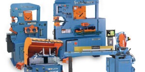
And yet finishing, in many cases, has not been of the required quality, although a solution from Sandvik Coromant (Fair Lawn, NJ) addresses this issue. The CoroMill® 790 features advanced edge, insert, seating and clamping technology to provide an alternative for aerospace manufacturers.
CROSSING BOUNDARIES
In the process of developing an end mill concept for aluminum machining, several parameters were acknowledged as being crucial to a breakthrough for radial milling with indexable inserts. Among these were good chip formation, a smooth cutting action, high metal removal rate, low power consumption regarding quantity of material removed, high surface finish with minimized mismatch, and strong tool security at rapid spindle speeds.
Conventional indexable insert edges have tended to be comparatively blunt for aluminum machining, leading to a plowing effect, particularly when cutting thin chips in finishing operations. The entry of the edge into the cut has also tended to be abrupt, leading to sudden gains in cutting force. Combined, these properties can lead to excessive tool deflection and power requirements.
The problem is complicated further by the need for an edge that must be both positive and sharp for finishing, and capable of high removal rates when roughing. Subsequently, there is a real demand for a fresh approach to the indexable insert concept that concentrates on resultant cutting forces, edge entry, chip formation, stability, insert location and clamping.
The abrupt impact of a milling cutter’s edge when it engages with a workpiece will create tool vibration. The resulting cutting forces are very much dependant on the thickness of the uncut chips, which is proportional to feed.
The initial tool vibration has a tendency to alter this thickness, which then might continue increasing as fluctuations in force feed larger vibrations back into the system. Cutting force direction and amplitude largely determine vibration tendency. This form of regenerative vibration is more commonly known as chatter, and if unaddressed, force amplitude can rise, leading to poor surface finish. In some cases even the cutting edge, tool and machine spindle can be put at risk.
Cutting force amplitude has to be dampened at the start and again later if it begins to grow during the cut. However, in most cases this has to be achieved through insert geometry design.
The development of a model that calculates and predicts cutting forces accurately was one of the principal foundations for a patented insert geometry design. Innovative FEM-simulation helped provide several answers to the combined design of edge-line, rake angle and chip-former, as well as the creation and optimization of an edge feature on the insert clearance face: a precision primary relief land.
Subscribe to learn the latest in manufacturing.

Industry News