High Speed Cutting Process Optimization: How to Cut Even Faster
New functions have helped to reduce the cycle times required for 3D laser cutting, outside of the time when the laser is actually cutting. But even with these new technologies, applying the established best practices and tricks can often reduce those times even more.
Posted: November 1, 2012
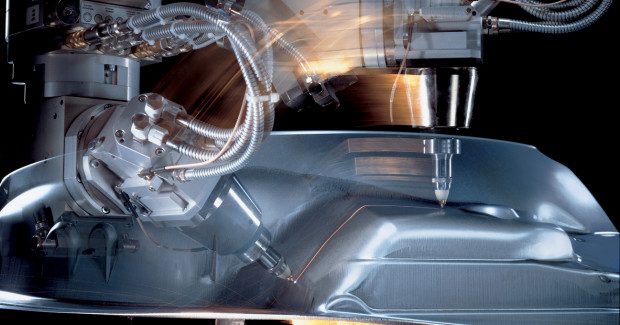


Productivity, and therefore cutting speed and machine dynamics, have always been key factors in laser cutting high volume, thin gage parts – especially in automotive manufacturing. These criteria have become even more important in the booming market of 3D laser cutting of hot formed body in white parts.
Cut quality is usually acceptable if no dross remains on the part after cutting. So the limits of the cutting process can and are pushed quite far in order to optimize cycle time and therefore productivity, to get the most out of the equipment.
NEW MACHINES: NEW FUNCTIONS
Modern 5-axis cutting systems have seen many improvements over the last couple of years: High laser power for cutting with CO2 lasers became available and opened new processing windows for cutting thin gauge material. Plasma-assisted nitrogen cutting was born, allowing processing speeds up to three times faster than what could be achieved with “old-fashioned” fusion cutting with the same assist gas.
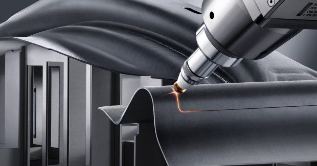
These cutting speeds could be met or even be exceeded with the advent of high brilliance, high power solid-state lasers. High speed, plasma assisted cutting speeds achieved by 5 kW CO2 lasers can be matched or even exceeded with only a 3 kW solid state laser, with a wavelength of 1.03 µm – at a much more attractive wall plug efficiency.
New functions help reduce time required for the machine to process the part, outside of the time when the laser is actually cutting. Examples of this include gas purging while positioning, piercing on the fly, controlling machine dynamics, additional fast axes in tool direction and automatic adoption of the laser power to the actual cutting speed in the tool center point. Even with new technologies, however, the established best practices and tricks often still apply.
NC PROGRAM GENERATION: ENSURE A HEAD START
Almost all NC programs for cutting of 3D thin gage hot formed parts are generated in an offline programming system which imports 3D CAD models of the fixture and parts into the system, subsequently generating the NC code. Although these programming systems provide many automatic or assistive functions, one should not underestimate the knowledge accumulated by a well trained programmer with practical experience.
One of the keys to generating fast and accurate programs is to decide the sequence in which contours are cut. The cut sequence should be determined after the parts are appropriately placed to avoid reorientation of the processing head, allow scrap to fall safely and with consideration of repeat loading of the part.
The main considerations when determining cut sequence are to minimize positioning moves and machine re-orientations and to take reference -related factors into account last, such as keeping the part clamped as long as possible and cutting the contour with the locator hole for a reference pin. Instead of a sequence of linear segments, programs should use round movements (arcs) to facilitate smooth transitions wherever potential collisions need to be avoided.
Selecting a good reference point for the workpiece coordinate system (WCS) is also beneficial. It should be a position that can be clearly and precisely identified both off-line in the programming system and on-line on the real fixture. Reference pins, for example, are a good choice. A final simulated run of the program is also recommended; if it looks smooth, it is usually fast, too.
TRANSFER TO MACHINE: SHOW TIME!
The first step in transferring the program to the machine is to teach the WCS as precisely as possible. All clamp movements need to be programmed before running a slow motion test run. Watch the test run to get a good understanding of potential problems. If the program runs without unexpected moves or collisions, the next step is to make sure the NC program fits the part position and part orientation as closely as possible.
Minimizing the differences between program and real position is time well spent. Some modern machines display the difference between the programmed tool path and the actual position. This function gives a great indication of how the program should be adapted. The closer the fit, the better the first part dimensions. More importantly, the better the cut quality, the less the parameters will need tweaking. This might be surprising at first, but if the program and part match the processing head will be perfectly oriented and beveled cuts will be minimized.
While sometimes beveled cutting is necessary to avoid potential collisions, cutting with more than about 10 deg off-normal results in decreased cutting speed in order to maintain cut quality.
TWEAKING THE PARAMETERS: MAKE IT PRETTY
One fact should already be understood: Quality results at high speed are only achieved after thorough set-up of the machine. Let’s start with an undamaged nozzle that is perfectly centered to the laser beam. This is particularly important when cutting with a solid-state laser where it should be no more than 0.05 mm off-center. In order to maintain cut quality, the focus position should be determined when the lens is replaced. It is also important to make sure the processing head is set up correctly and the offset values are accurate.
Then it’s show time! Besides checking the cut part dimensions, this is all about cut quality and minim dross. As a rule of thumb, the focus position should be in the lower third of the material thickness. From there it can be varied in small increments to find the optimal value. Most problems occur when the head travels around a 3D corner. Here, the distance control may react to an incorrect nozzle stand-off which, in turn, causes dross. This can be corrected manually to maintain a constant stand-off.
Laser power control can also improve cut quality in these areas. This function interpolates the laser power between two or more reference points according to the actual speed in the tool center point. As the machine dynamics reach their limitations in tight corners the cutting speed drops. Without this, too much laser power would be released causing dross on the part.
By setting the reference points correctly, the laser power adjusts to changes in speed, and cut quality can be maintained. Those reference points can be determined by cutting long thin stripes in an even area of the part. Manual correction of the nozzle stand-off and the laser power control in combination should resolve most of the problematic areas.
Now everything should be set to run production.
Subscribe to learn the latest in manufacturing.

Industry News