An Application Guide for Scissor Lifts
To select an appropriate scissor lift for a specific application, here is the basic information that must be considered, including capacity, the nature of the load, the means of loading and unloading, the travel and lowered height, the platform size, speed requirements, power and duty cycle requirements, and more.
Posted: October 30, 2013


The following discussions are used to clarify the meanings of these topics, point out special considerations to be aware of, and provide a common vocabulary.
CAPACITY
The capacity of a unit is the total weight being placed on a unit and consists of the total live load + the total dead load as described below.
Live load weight and description: Live loads are the items that will be placed on the unit and removed from the unit. It is important to know the maximum weight. It should also be noted if the load will be unbalanced due to a lopsided or irregular configuration or a loading operation that can cause temporary uneven loads.
Dead load weight and description: The dead load is the weight that is applied to the unit on a permanent basis such as conveyor, weight scales, or fixtures. A good description, including how the dead weight will be supported by the platform and attached to the platform, is necessary so that engineers can determine if the structure of the standard platform can satisfactorily support the incurred loads without deflection or twisting. Any unbalanced loads such as offset conveyor drive motors must be mentioned so that the center of gravity for fully loaded and minimally loaded configurations can be determined.
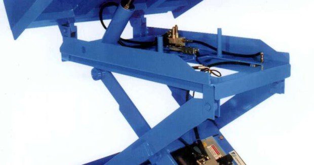
Here are demonstrations of lift tables for palletizing operations: the SL-S with mechanical spring operation, the SL-P with pneumatic spring operation, and the PL with electric hydraulic operation. All three of these lifts feature more rugged construction than other offerings at extremely competitive pricing.
NATURE OF THE LOAD
This requires a good description of what the load consists of, the weights of the load components, the center of gravity of the load, if it is not centered on the load, and the physical dimensions of the load. The concern here is that off-centered loads can reduce lift life dramatically if not properly handled. They can put more severe demands on a structure than the simple lifting effort.
In all cases, assume that the worst loading to be encountered with the lift in motion will be no more than half of the load on half of the platform. The critical information in these cases is where the center of gravity of the load will be in relation to the center of the platform (center of the supporting leg structure as described by the minimum platform size) when the unit is put in motion. It is ideal to see the center of gravity of a load in the center of the platform.
Fork truck counterbalance weights and oil filled transformers are just two examples of loads that present severe off-center loads when their foot prints are nicely centered on platforms. Off-center loads due to loading or unloading operations while the lift is stationary are discussed as a separate topic below. There are many ways to handle off-centered loads satisfactorily, provided that the requirements are understood by engineers early in the selection and design process.
MEANS OF LOADING AND UNLOADING
How loads are transitioned onto and off of the lifts can be the critical factor in choosing an appropriate lift design. These movements determine the “edge loading” and/or “impact” that the structure must sustain and they may contribute to off-centered load conditions during the lifting cycle. The most common ways in which loads
are transitioned on and off lifts are as follows:
- Rolled on/ rolled off – with a wheeled vehicle or cart
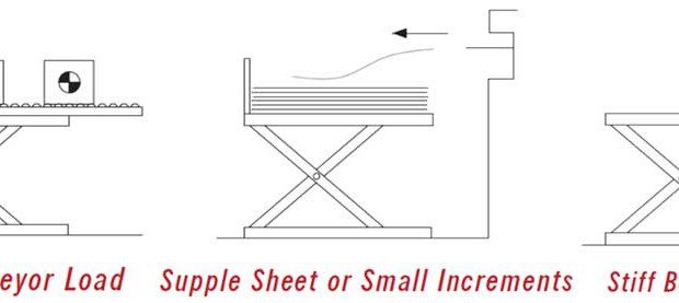
- Slid on/ slid off – as in sheet feeding operations or conveyor operations
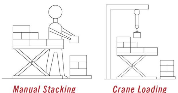
- Placed on/ picked off – as in stacking operations or crane loading
Before moving into these specific applications, unit capacity ratings must be considered.
GENERAL DISCUSSION
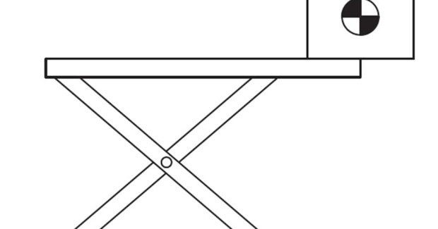
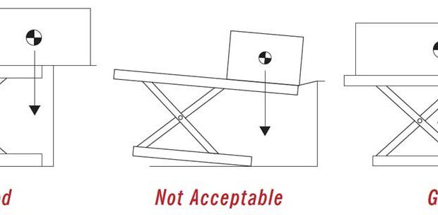
“Edge loading” capacities of lifts are generally stated in this catalog as a “static” capacity. This is equivalent to a uniform stiff load teetering on the edge of a minimum size platform edge with no allowance for any impact. This is illustrated in Figure 1.
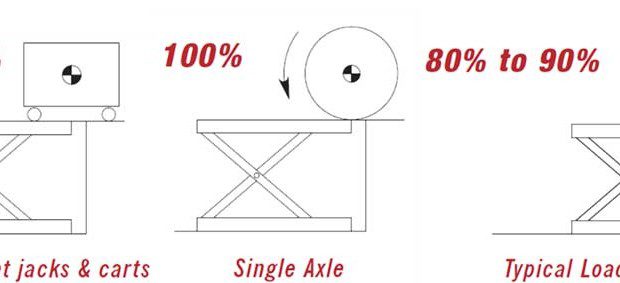
In real life this condition rarely exists and the “static” rating in the catalog must be modified with an appropriate multiplier for the various types of “dynamic” or moving loads that will actually be encountered.
EDGE LOADING
What matters most with edge loading is what loads will pass over the edge of the lift in anything other than the fully lowered position. In the fully lowered position the baseframe, cylinders and leg assembly are fully supported and only the overhang of larger than minimum tops are subject to any bending forces. Therefore, a maximum capacity load may pass over the edge of a minimum size platform of a fully lowered lift and there are no concerns about the edge loading of the lift. If the platform were larger than minimum, then engineers would have to ensure that proper supports were placed under the platform to prevent any potential deflecting or bending.
DERATING FOR OVERSIZE PLATFORMS
The “static” edge load capacity of over-sized platforms must be derated because the oversize platform overhang acts as a lever, increasing the forces incurred by the supporting leg assemblies for any given weight. Edge loading capacities are derated by the rule of thumb of two percent per inch for every inch that a platform is wider than minimum width and for every inch that it is longer than minimum length.
For example, consider a minimum platform size of 24 in x 48 in. If this were equipped with a 48 in x 54 in platform, the unit would have the side edge load capacity reduced by (48 in – 24 in) x 2 percent = 48 percent. The end of platform capacity rating would be reduced by (54 in – 48 in) x 2 percent = 12 percent. There are many variables that go into the actual edge load capacities, but the two percent rule of thumb is a good general rule to use.
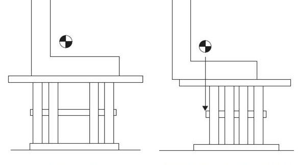
SIDE LOADING
Most scissor lift designs have much greater strength over the ends of the lifts than they have over the sides of the lifts. For this reason, loads should travel over the ends of lifts, parallel to the lift legs, rather than over the sides when the lifts are anything but fully closed.
INCREASING SIDE LOAD CAPACITY
EW (extra wide) models and VW (very wide) models have been developed for many series of lifts. The wider units are built with wider stance leg assemblies, which means that for a given platform size the side edge loading does not have to be reduced as much as their narrower brother.
Subscribe to learn the latest in manufacturing.

Industry News