Direct Load Position Sensing with Secondary Feedback Encoders
To help verify machine tool accuracy in closed-loop motion control systems, direct load monitoring using secondary feedback encoders eliminates common sources of position error — mechanical backlash, non-linearity, and hysteresis — and saves money along the way.
Posted: March 5, 2014

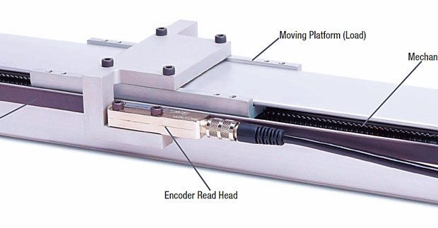


In closed-loop motion control systems, direct load monitoring using secondary feedback encoders eliminates common sources of position error — mechanical backlash, non-linearity, and hysteresis — and saves money along the way.
MOTION CONTROL FUNDAMENTALS
In the field of automation, a motion control system consists of mechanical hardware coupled to a prime mover, the operation of which is governed by a computerized controller that compares the command position to the indicated load position. Typically, the indicated load position comes from a rotary shaft encoder or linear position encoder.
In response to a difference between the command position and indicated load position, the controller generates a drive signal that is fed to the device that regulates the speed and direction of the prime mover — for example, an electronic amplifier driving a servomotor.
This process of reading position, comparing it to the command position, and then driving the prime mover until it is positioned correctly is called closed-loop motion control. Besides position, other controlled variables such as velocity (the mathematical derivative of position) or force can also be measured.
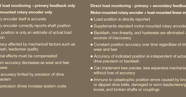
With respect to position and velocity, the accuracy of the controlled motion – from the perspective of the load — is highly dependent upon how closely the indicated load position matches actual, real-world load position. The indicated position is always a facsimile of the actual load position. Due to various error-inducing factors, the indicated load position never exactly matches the actual load position. The nature of the induced position errors depends on the architecture of the position encoder and how it interacts with mechanical drive hardware.
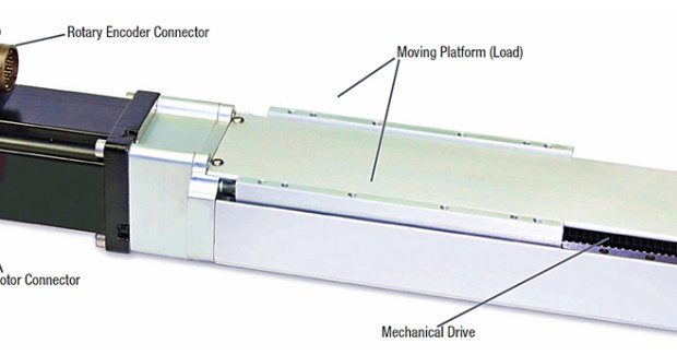
For electric, closed-loop motion control systems, common system architecture features an electric motor as the prime mover directly coupled to a rotary shaft encoder as the load position sensor. The load may be connected to the electric motor through a variety of mechanical elements such as acme, lead, or ball screws, rack-and-pinion systems, or toothed sprockets with toothed drive belts.
In this architecture, the true standard of measurement is not the rotary encoder, but the drive system itself. The rotary encoder accurately indicates (within its specifications) the drive motor’s shaft position. To implement closed-loop position control, an assumption must be made that X revolutions of the motor/encoder result in Y units of displacement at the load. For example, it may take 1,800 revolutions of the motor for the load to travel 12 in, which can also be expressed as 1,800 rev/12 in = 150 rev/in.
FACTORS CONTRIBUTING TO INACCURACY IN ROTARY ENCODER SYSTEMS
The relationship between motor revolutions and load displacement is only an average, calculated figure. The actual relationship along any given segment of the positioning system is dependent on the drive system’s mechanical precision: A high quality leadscrew may closely follow specified revolutions per inch, whereas a lower quality screw may deviate more substantially from the nominal value. Any deviation away from the ideal linear relationship between revolutions and displacement is called nonlinearity.
In addition to that of the screw itself, there are other sources of nonlinearity, such as mechanical compression or tension of the leadscrew under dynamic conditions of acceleration and deceleration, as the load inertia resists the impulses of the drive system. This type of loading can also dynamically stretch drive belts and cause dynamic torsional distortion of drive shafts. More dynamic motion and heavier loads magnify how much these factors contribute to overall system nonlinearity and resulting errors in load position or velocity.
Depending on the application’s accuracy requirements, thermal expansion and contraction of the drive system creates position deviations that must be quantified and compensated to maintain performance tolerances. Even in zerobacklash drive systems with little or no mechanical play, reversal of drive direction can impart a significant mechanical hysteresis error that arises from frictional forces and drive component compliance in shafts, leadscrews, thrust bearings, and so on.
COST DRIVERS IN ROTARY ENCODER SYSTEMS
The precision of this type of motion control architecture is at its peak when the system is brand new. However, as the system wears in and tolerances open, accuracy begins to deteriorate and continues to decline over the system’s lifetime. This means that the system must be designed to deliver excess initial system performance in order to guarantee specified performance over time, resulting in a higher initial system cost.
Furthermore, because motioncontrol system accuracy is determined by the quality and precision of the mechanical drive system — and not the rotary shaft encoder — it follows that tighter accuracy specifications force tighter specifications on the drive mechanism, imposing a cost premium for higher-end mechanical components.
Subscribe to learn the latest in manufacturing.

Industry News