Laser Beam Delivery and Focusing Optics
Some tips and best practices for maintaining a high production yield in micro welding.
Posted: March 5, 2014


Manufacturing engineers tend to devote a significant amount of time and energy to thinking about the laser, motion, tooling and their process, while sometimes overlooking the delivery of the laser to the workpiece, and the focusing of the laser. To maintain high production yields, it is extremely important to understand the basics of beam delivery and follow a few best working practices for implementation, standardization, and maintenance of the optical delivery components.
In many cases there is reliance on the system integrator or laser OEM to provide the necessary optical recommendations and support. To enable complete ownership of the process, it is critical to have a full understanding of beam delivery and focusing optics, machine and process qualification, to enable self-support and troubleshooting, especially when process/yield drift or process failure occurs.
LASER DELIVERY
Figure 1 shows the six essential components of a laser system. The laser must be “delivered” to the workstation. For lasers of a certain wavelength, around one micron (corresponding to neodymium-doped yttrium aluminum garnet (Nd:YAG), fiber and diode), the laser can be delivered to the workstation by a flexible fiber optic cable. This offers great convenience for integration because the flexible fiber can be routed by whichever orientation is best for the system. Typically, the fibers are between 5 m to 20 m in length, so the laser can be situated some distance from the workstation if required.
Launching the Laser Into the Fiber
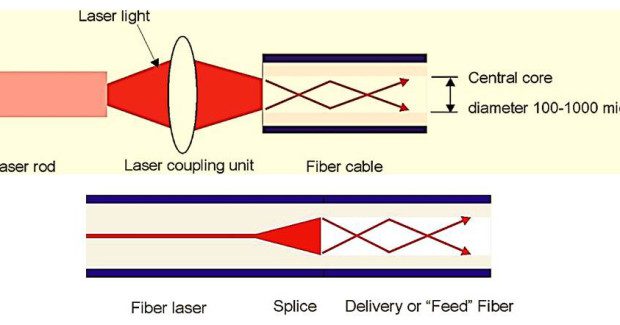
For a Nd:YAG laser, a laser coupling optic is always used to launch the laser into the fiber, with one side accepting the laser and the other containing the fiber connection. There is usually a one-time fiber launch setup, though alignment should be verified by delivered power or pulse energy and beam mode if possible when changing or switching to a small core diameter fiber (< 300 microns).
Thinking about implementing a laser micro welding process in your plant? This webinar, recorded by Miyachi Unitek covers all the basics you need to consider to ensure success:
• Materials & plating selection
• Joint Geometry
• Fit-up tolerances
• Tooling
• Applications overview
• Laser System implementation
An external laser coupling optic can be used for a fiber laser, or the delivery fiber can simply be spliced into the lasing fiber. The disadvantage of an internal splice is that replacement of a damaged delivery fiber may require returning the laser to the supplier for repair. The beam coupling method enables fiber replacement in the field with a quick changeover – very important for production uptime.
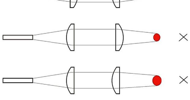
Figure 2 is a schematic showing the launch of the laser into the fiber. The top graphic shows the laser coupler method for Nd:YAG and fiber lasers, and the bottom shows the splice method, for fiber laser only. The delivery fiber has minimal power loss due to very efficient total internal reflection of the laser inside the fiber.
Routing of the Fiber to the Workstation
Make sure the delivery fiber does not exceed its minimum bend radius (usually around 6 in, or 150 mm) because bending a fiber beyond this limit may overstress the fiber, leading to potential power losses or in the worst case, a catastrophic failure. It is rare for a fiber to fail, but it is nonetheless serious. The potential can be precluded by equipping the system with fiber breakage detection, which can sense when the fiber has been damaged. The more advanced detection systems test the fiber prior to firing of the laser.
Best working practice is to route the fiber above ground, not touching the floor between the laser and workstation to avoid the possibility of crushing the fiber, then coil and hang excess fiber length at the workstation. If the focus head will be moving, give sufficient slack, and again make sure the fiber’s connection to the focus head avoids exceeding the minimum bend radius.
Subscribe to learn the latest in manufacturing.

Industry News