How Your Selection of Press Brake Tooling Affects Manufacturing
Have you ever considered how standard tooling impacts the design of a part?
Posted: April 15, 2015


During a recent conversation in a design group meeting, I overheard someone say, “It looks great, let’s bend it up!” Often, issues affecting the manufacturing process arise, requiring the design group to make adjustments to their design. Before bending a new part, it is important to look at the press brake tooling selection, material choice and the machine to consider how it will affect the manufacturing process. This article will use an application example to look at the way standard tooling impacts the design of a part.
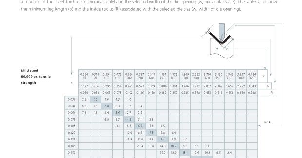
The company recently purchased a 95 ton press brake and is looking to bend new parts in .250 in mild steel. To keep the parts aesthetically pleasing, the design engineers will use an air bending technique so the material never touches the bottom of the lower tool (die). The manufacturer must first as questions such as: How many long can the bend be with this machine? What is the minimum flange length achievable? What is the resulting radius based on this flange length? There are numerous programs and apps on the market to help answer those questions. Alternatively, the fabricator can use a chart, such as Chart 1 shown here, to help determine the limitations of the machine.
Start with the recommended tooling. The attached bending force chart uses the rule that the die width should be six to eight times the material thickness. To bend .250 in material, the operator needs a die width between 1.5 and 2 inches. The chart recommends a die that is 1.969 in wide, but it also shows several alternatives. Using the recommended 1.969 in wide die, the press force is 15.1 tons per foot, the minimum flange length (b) is 1.476 in, and the radius (Ri) is .315 in. With this information we can now derive the maximum length for our machine (95 ton / 15.1 ton = 6.2 ft). These numbers are a close approximation as variance in material properties might make them change.
With this information, the engineer now knows that when bending .250 in thick parts with this press brake, all flanges must be greater than 1.476 in long, and the bend length must be shorter than 6.2 ft. Designing anything outside this range, such as part with a one inch flange, or an eight foot long bend will not work.
GOAL: DESIGN A LONGER BEND
What if the design engineer requires an eight foot bend? To determine the press force needed for an 8 ft bend on a 95 ton capacity machine, simply divide 95 tons by the bend length needed. (95 ton / 8 ft = 11.875 tons per foot). A die with a wider opening will require less force to bend the material so, once again, we consult the chart to determine the appropriate size. A die opening of 2.362 in reduces the required press force to 9.5 tons per foot. However, it will also impact the minimum flange length and the bending radii, since the part has to rest on the shoulders of the die. Since they will impact the part design, these tolerances must be recalculated. The minimum flange length (b) increases to 2.362 in and the radius increases to .512 in.
GOAL: DESIGN A SMALLER FLANGE
What if the design engineer needs to reduce the flange length to one inch? To achieve a smaller flange the die width must be reduced. This will increase the tonnage needed for the bend. According to the chart, achieving a minimum flange length (b) of less than one inch requires a die width of 1.181 in. With a new minimum flange length (b) of just .886 in, the press force increases to 25.2 tons per foot with a maximum bending length of 3.7 ft. It is clear that many factors come into play during part design. The design group must have the part criteria in mind before developing a new part so they are able to calculate the numbers and prevent major problems when bending the part.
TOOL SELECTION
When the design group is pleased with the part and all its criteria have been met, there are a few additional considerations before attempting the bend. The upper tool (punch) is selected based on its height, tool rating and shape. It is easiest to use the machine’s software to select a tool based on the part’s geometry, although it is also possible to make the selection with a side profile template or the tool itself, especially if a cardboard mock up exists. In some cases, it might be best to work with the tooling manufacture to create a custom tool.
Once the punch and die have been selected, use the offline programming software to test the bending sequences and bend allowances. Any issues, for example with box height or part geometry, will quickly become apparent. If no issues arise, the part is bendable. It is best if the design group also has access to this software to quickly and easily test various design options before moving forward with production. Programming the part offline will also ensure all operators use the same bend sequences and tooling when the part is manufactured.
Once all the pieces of the design puzzle are in place, develop the flat pattern based on the bend allowance values in the software. It is critical to use the same software, data base, or chart to develop the flat pattern for all the machines programmed since using different software for the laser can create problems during bending. For example, a part developed using a 3D CAD software will unfold using the bend allowances in that software package while the programming software of a punching or laser machine might use a different bend allowance and the press brake software would perhaps use a third. Invest the time initially to make sure all software uses the same formulas to develop the flat part or many quality issues will surely arise. By following the guidelines above, a manufacturer is best equipped to bend a perfect part on the first attempt.
Subscribe to learn the latest in manufacturing.

Industry News