Cold Machining with Ultrafast Lasers
Femtosecond and picosecond laser systems produce high quality small features with high dimensional accuracy, with minimal burring and debris that reduces or eliminates post processing. However, these systems are expensive, so choose the laser and system wisely. Here are some things to consider.
Posted: May 29, 2017


Ultrafast or ultra-short pulse lasers offer unique material processing possibilities because the laser’s pulse duration is less than the target material’s conduction time. This essentially means that cold machining of parts is possible, with material being removed by sublimation. This vaporization machining method offers advantages that simply cannot be produced by any other process: near zero heat affect, minimal burring and debris that reduces or eliminates post processing, high dimensional accuracy, and the ability to produce high quality small features in metals, plastics, ceramic and glass. However, these systems are expensive, so the laser and system choice must be carefully considered.
SHORTER PULSE DURATION: NO HEAT SIGNATURE
Like so many other laser technologies, the ultrafast laser came to life in a research lab. However, it was not long before the ultrafast laser’s pulse duration (which is significantly shorter than commercially available nanosecond lasers) drove interest in its use for micromachining and material processing. The ability to process almost any material with almost no heat signature offered a unique manufacturing tool that enables product innovation and development. In some cases it even results in cost reduction. Which ultrafast laser technology is best for particular applications? Ultrafast lasers are divided into two main categories: A picosecond (PS) laser emits optical pulses with a pulse duration around 10 picosecond – just over one trillionth (10-12) of a second, or one millionth of a microsecond. A femtosecond (FS) laser emits pulses that are one around 400fs, less than one trillionth of a second in duration.
It is worth noting that the term “ultrafast” does not refer to the material removal rate. In fact, quite the opposite is true, which is why these lasers excel at processing material thicknesses of less than 0.01 in (250 microns). Thicker materials can be processed, but then one must consider cycle time more closely. The processing differences between PS and FS lasers can be very subtle in some instances and in others very apparent. When used to process metals, the difference is subtle; the FS laser offers zero topside burr with slightly better defined features and lower surface roughness. The FS laser can also process a greater range of plastics. PS lasers typically require green or UV wavelengths to process plastics effectively. Quality comparison between PS and FS is material-dependent. When the absolute best quality is needed, FS is the clear choice. However, PS lasers tend to machine faster, so the question becomes, “How good is good enough for the process?”
https://youtu.be/G1kSeFphMds
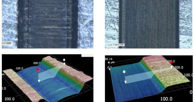
Understanding which laser works best for an application can only be determined through parts testing. As part of defining the application and system, we typically run samples on both FS and PS lasers and on multiple wavelengths for both lasers, as needed. Analysis of the process quality, removal rates, and cycle time all need to be weighed carefully between the two lasers. The typical price of an ultra-short pulse system is in the range of $400,000 and above. So before embarking down that road, users should clearly understand their return on investment so that they can justify the system purchase in terms of cost reduction, unique processing capabilities, or in many cases, both. The final decision on which one to select is made after an iterative process that usually includes a number of short runs of parts. Figure 1 compares PS and FS lasers machining a 100 micron wide channel in metal. Using a similar material removal method and cycle time, the FS laser produces cleaner edges and a smoother base.
SELECTING THE PROPER ULTRAFAST WAVELENGTH FOR SPECIFIC MATERIALS
Both PS and FS lasers offer wavelength choices of infrared (IR), green (GR), and ultraviolet (UV). Certain wavelengths work best for specific materials, and/or one can also select the wavelength based on a particular feature size required. The smallest focus spot size achievable is directly related to the wavelength. This means that if all things are equal, a UV laser will focus to a spot size one-third the diameter of an IR laser. In this discussion, we refer to the wavelength by name (IR) rather a wavelength number (1,030 nm), since different laser technologies operate at slightly different wavelengths. Each of the FS and PS lasers can be offered with multiple wavelengths available from a single laser. This option is typically used more for research and development rather than for production systems, where single wavelength point of use machines are used for a specific material and process.
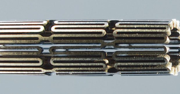
Examples of where different wavelengths matter include picosecond IR for glass cutting and picosecond GR for medical plastics, such as PEBAX. The use and argument for different wavelengths matched to different materials is less obvious for FS lasers. Many people originally thought that the normal absorption dependency-to-wavelength would no longer apply with such a short pulse duration, and that “multi-photon absorption” would dominate. This has not proven to be the case for certain plastics: polymer stents are a good example. Not only is the processing quality and cutting speed better using FS GR, but the processing window is also larger using green compared to IR. When machining small or blind features on plastics down to the micron level, the green wavelength can provide a more stable process.
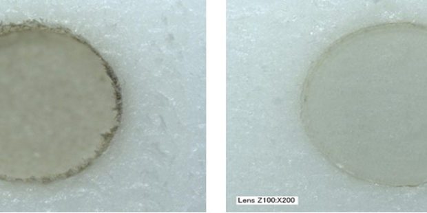
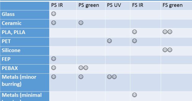
Figure 2 is a comparison of blind drilling PET material with picosecond IR (left) and picosecond UV (right). The processing time is the same, but the hole depth is three times better for picosecond UV, with less charring. The only reason to select a different wavelength for both PS and FS laser processing of metals would be for feature size. From a processing perspective, there is little difference between IR, GR, and UV. Table 1 provides a general overview of the best wavelength choice for particular materials.
INTEGRATION OF ULTRAFAST LASERS INTO MANUFACTURING
The key feature of the ultrafast laser is its ability to process material to high dimensional accuracy. This means the first system requirement is to support that level of precision. However, all the best hardware in the world will not provide a stable system if the environment in which the system is placed is not stable, specifically for temperature variance. In the world of microns of precision, temperature variance beyond a few degrees will cause issues, not only to fixtures and stages, but also to the laser’s pointing stability. For example, each degree Celsius of temperature change would change a 12 in (300 mm) length of aluminum by 0.0003 in (7 microns). Therefore, the machines need to be housed in a well-controlled and air conditioned space.
An ultrafast laser system is composed of several elements: the laser, an optical path to deliver the laser to the focusing optics, focus optics, motion, vision, debris control, and tooling. Each must be carefully considered as part of the optimal system solution. The laser is guided to the focusing optics using mirrors and a variable beam expander, which provides flexibility in changing the beam diameter entering the focus optics and therefore the size of the focus spot. There are two reasons this is needed:
- First, each laser’s output is a little different, so unless the process was qualified with the exact same laser to be used with the system, the variable beam expander can be used to tune the final focus spot size.
- Second, mostly with regard to flexible setup machines, the variable beam expander can change the focus spot size for different applications. Knowing and maintaining the position of focus on the part is very important, because in many cases the laser’s depth of focus or Z height tolerance can be less than 0.01 in (250 microns). If tooling cannot maintain this tolerance, non-contact laser distance sensors can be used to close the loop with a Z stage to keep the part in focus.
The focusing optics can be a fixed focus head or a scan head. The fixed focus head focuses the beam only and relies on stages to move the part or itself, whereas the scan head has small moving mirrors that direct the beam in a certain sized XY area and also focuses the laser. The advantage of the scan head is that it can move the laser very quickly over small areas, which is typically required for many micromachining applications. All stages are always linear drives. For scan heads, the part remains stationary during processing, but it can be indexed to another processing area as needed. The area the scan head can process is usually relatively small: around 40 mm x 40mm. It is important to select scan heads with digital feedback, otherwise the positional errors (particularly from thermal drift) can really push up the processing positional tolerances.
To process features exactly where they need to be, machine vision is usually an integral part of these systems. The vision in itself can require significant development with regard to camera resolution, lighting style, and wavelengths. In most cases, features can be positioned to within ± 5 microns of a target location and even better when the fiducial location is close to the feature location. As noted earlier, there can be some wander of the laser, so this also has to be considered. A datum procedure is needed to know where the beam is in space. Debris management is one aspect of these systems that can be easily overlooked. Where does all the removed material go, and does it matter if it lands back on the part? These ultra-fast lasers produce nano-particles that tend to be charged and, as such, tend to stick to surfaces. In some cases these particles can be cleaned using an ultrasonic bath, but in other cases the system may require use of extraction, possibly using multiple extraction methods.
As with any precision process, tooling is a key factor. For thin planar parts, vacuum chucks are commonly used. Non-planar parts usually need custom tooling. In each case, location features and fiducial features can be used for part location and feature-to-feature location for vision systems.
SUMMARIZING SYSTEM NEEDS
Before moving to system fulfillment, one must satisfy a number of milestones, including application feasibility, application development for production, producing a sufficient number of pre-production parts, and, most importantly, developing a clear technology solution route for a production machine. There is value in completing these steps with a single supplier, because the system concept and design are executed from the foundational knowledge associated with developing the application process.
Subscribe to learn the latest in manufacturing.

Industry News