Using Advanced CAD/CAM to Optimize Machining of Complex, Progressive Stamping Dies
Stamping dies feature complex geometries with tight tolerances that can take time to produce due to tooling changes, breakages, or programming challenges. This machine shop shares some insights on how they use powerful CAD/CAM software for easier and more functional programming that minimizes time and costs.
Posted: December 21, 2017


Roughly 30 miles north of Milwaukee, WI, on the banks of Lake Michigan, lays the village of Saukville, with a population of about 5,000. Roughly 50 of those people are responsible for running Oldenburg Metal Tech, Inc., a 25,000 sq ft machine shop that specializes in complex, progressive stamping dies. But that’s not all. They also produce welding fixtures, production parts, and prototypes for anything from automotive steering brackets and frame components (including some dies for a leading electric car manufacturer) to dental trays. Volumes can run in the hundreds, as is the case with stamping die components and production plate work, or into the thousands for small production components. The stamping dies feature complex geometries with tight tolerances that can take time to produce due to tooling changes, breakages, or programming challenges.
In order to minimize time and costs, Oldenburg invested in ten vertical machining centers, four turning centers – one with live tooling dedicated to production machining – and a powerful CAD/CAM software package that makes programming easier and more functional. Vinny Decker is their only full time CNC programmer, and he explains how most of the jobs that come through have complex geometries with tolerances within 0.001 in to 0.002 in, but can go within tenths of an inch when necessary. “We do so much hard milling here,” he says, “that with some of the tighter tolerance or 3D work, the stamping box will be heat treated and I’ll need to perform a secondary hard mill operation to achieve certain tolerances, finishes, etc.”
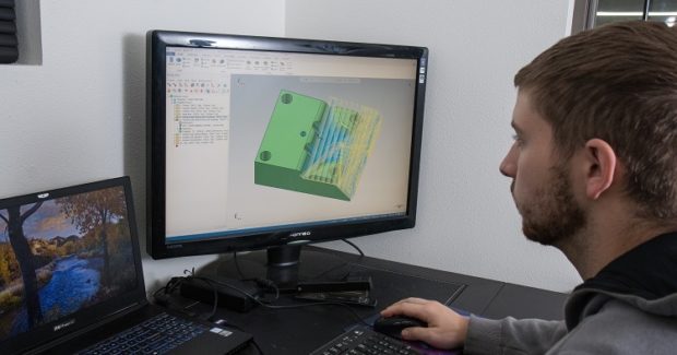
Decker relies on the different functions of Mastercam software from CNC Software, Inc. (Tolland, CT) to get those tolerances and finishes while removing material at record rates. Dynamic Motion technology allows the shop to push the machine tools to their speed limits. Through proprietary algorithms programmed into the software, the tool remains constantly engaged with the material, automatically sensing changes in geometries programmed into the high speed toolpaths by Decker. “We don’t do a whole lot of old school machining methods here,” he smiles. “A lot of what we do is high speed area roughing with high speed mills. The high speed waterline and raster finishing paths are done with carbide end mills and saw mills.” Dynamic milling is also used for deep pockets (i.e. cut-off plates, contours, etc.), with the machines removing material at a rate of 150 ipm to 200 ipm. Typical end mill and ball mill sizes range from 1/8 in to ¾ in while the high speed ball mills for roughing range from ½ in to 2 in.
These toolpaths have allowed Oldenburg to take on larger jobs than were possible when Decker joined the company five years ago. “When it comes to die building, we do dies that are double the size of what we were doing a couple years back,” states Decker. “The blocks are much larger, requiring a lot more 3D contouring. We now do more hard milling for tighter tolerances. A block that might have taken us 20 hours to machine before now takes us eight hours to 10 hours because the different types of toolpaths can efficiently cut down on time when machining certain features.”
The software’s Verify feature also provides Decker and the machinists with the confidence to run their machine tools at high speeds without worrying about tool and part breakage, or damage to the machine. “I verify every program I write because there are days where I’m programming 30 parts to 40 parts per day,” notes Decker. “I have all my tools created exactly how they are on the shop floor so that I know what to expect and the machinists know what to expect.” He “collision checks” parts where there might be some deep pockets or 3D contouring. In the event a tool needs to be relieved, Decker sees that as well and alerts the machinist. He also uses Verify’s compare feature to ensure that he didn’t accidentally hit something in the toolpath. The Accurate Zoom feature allows him to get an idea as to what the finish will look like. He uses stock models on bigger parts with a lot of toolpaths if he doesn’t want to verify an entire part. “I might create a stock model to go off the roughed in part and then verify my toolpath off the stock model,” he adds.
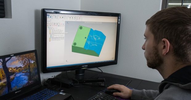
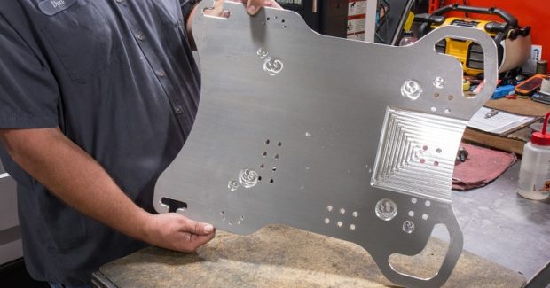
Oftentimes, Decker receives wire frame part prints for production or prototype parts and needs to create a model off the wire frame. The software makes this easy to do and the solid model is saved for referencing in the event the job is repeated or modifications need to be made. His favorite software features are found in the Model Prep function because they are simple to use and save him a lot of time. “A couple of years ago, I might not have been able to close up a surface or fill in holes on a 3D surface,” he recalls. “At that time, I would have to go to our designers and ask them to create a separate model without the holes in order to run 3D paths on it.”
Decker said that 99 percent of the time he can suppress any feature on the solid model he chooses. He can extend 3D surfaces, move them up and down to add more clearance, or add more stock if necessary. “I don’t really touch surface modeling anymore with Model Prep features,” he says. By eliminating the need to create a separate surface model, he saves anywhere from five seconds to an hour in programming time.
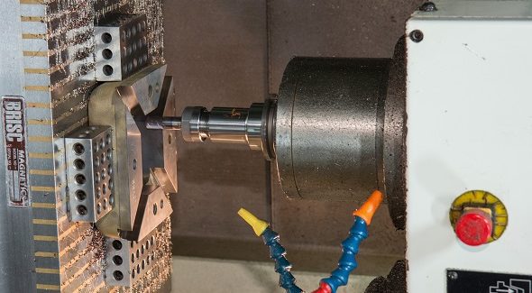
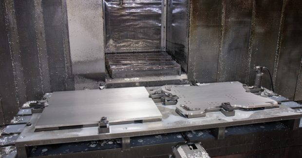
Oldenburg recently machined 16 large, complex 3D stamping blocks measuring roughly 24 in x 16 in or so, and 4 in to 5 in thick. The entire top of the blocks featured 3D contours in small radiuses. According to Decker, it would have been impossible to machine them just a few years ago. The surfaces were roughed, heat treated, and hardened to 60 Rockwell. The entire top surface was then hard milled. The total process took about 20 hours per time block, including figuring out which of the many toolpaths available in the software would work best and the different cutter technology for hard milling. Decker had to account for the finishing process, so he took all of the 3D surfaces and projected them up to about 0.0020 in to reflect the extra stock needed. The rest of the programming went like this:
- Decker programmed a raster path at zero to finish over the projected surfaces, then re-machined to the raster path. “I would do re-machining to that raster path on those surfaces, but my selection for my drive geometry would be to where the model actually needed to be, so it would only cut where it needed to. This eliminated air cutting.”
- After machining the stock down to 0.004 in to 0.005 in, Decker rastered over the entire block with a 3/8 in ball mill and ½ in ball mills to achieve a good surface finish. He then programmed a high-speed pencil toolpath and removed smaller radiuses and other geometries using 3/16 in and ¼ in ball mills.
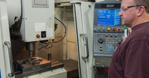
All of Oldenburg’s ten vertical machining centers are driven off of the software’s Tool Library, where 100 tools, each with a dedicated number, comprise the shop’s master library. Decker left a couple of open spots for the oddball tool that might be needed down the road. Having these tools at the ready saves him valuable time. His cost savings are also significant. “Because you can leave less stock and get the part closer to the point to where it’s actually going to be finished, you don’t have to waste time when it comes to finish hard milling,” he explains. “When a block is 60 Rockwell you don’t want to be taking off 0.050 in to finish. A lot of times, I’m only taking off 0.010 in at the most to get the part from roughed to finish. It obviously saves program run time, but we also see a huge cost savings in tooling.”
Decker relies on local reseller ShopWare, Inc. (Elgin, IL) for support when questions arise and to train machinists in the software’s basic milling functions so they have some familiarity at the primary level. And he is committed to explore around the software during lull periods to discover additional functions and features that will make his work easier. “It pays to invest a little of your time in learning the features because it’s going to save you a lot of time down the road,” he says.
Oldenburg Metal Tech, Inc., 775 North Progress Drive, Saukville, WI 53080, 262-284-6384, oldenburgmetaltech.com.
CNC Software, Inc., 671 Old Post Road, Tolland, CT 06084, 860-875-5006, www.mastercam.com.
Subscribe to learn the latest in manufacturing.

Industry News


