Three Ways to Optimize the Automated Brush Deburring Process
Want to reduce costs, improve process consistency, simplify part assembly, increase edge strength and create a more uniform finish? A wide range of operations are good candidates for a switch to automated deburring, and following these steps can help optimize the process for efficiency, quality and productivity.
Posted: May 20, 2018

In many manufacturing operations the deburring of metal components is critical to the overall process, as it can impact productivity and quality, which both affect the bottom line. Deburring components helps simplify part assembly while also providing greater edge strength and, in some cases, a more uniform finish. A wide range of operations are good candidates for a switch to automated deburring, especially those in high volume production applications where deburring parts by hand is difficult and time-consuming. So how can shops ensure optimization in the automation of a deburring process? Consider these key best practices to help deliver results, from cost savings to improved uptime and productivity.
STEP NO. 1: CONSIDER THE UPSTREAM PROCESS
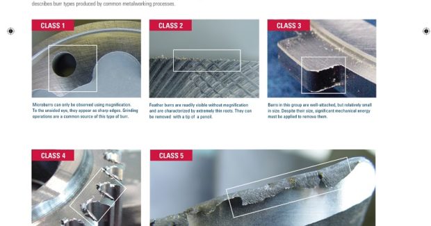
Burrs are raised edges or sharp pieces of material on the part that can be generated in various ways during the manufacturing process. They are typically produced by tools used in the upstream process, such as during CNC machining or metal forming and cutting operations. The deburring process removes these pieces and smooths rough edges. Understanding the best- and worst-case burr geometries that can be produced during the upstream process is critical to proper deburring. The tools that produce burrs wear with use, so burr size varies over time and the tools used for the actual deburring process also wear over time. All of these factors play a role in a burr’s geometry and its root thickness.
The first key step in addressing these variances is to stabilize the upstream process as much as possible. The automated deburring process should then be designed around the worst-case scenario for burr geometry. This helps ensure optimal process stability and consistency in finished parts. Remember, an automated process cannot look at a burr like a human can to decide whether to deburr twice as long as normal. So although deburring processes can be designed to handle great variability in incoming parts, these processes tend to be more expensive, have longer takt times and may require more frequent operator input. Reducing the variation of incoming parts is highly recommended.
STEP NO. 2: UNDERSTAND MATERIALS AND PARTS
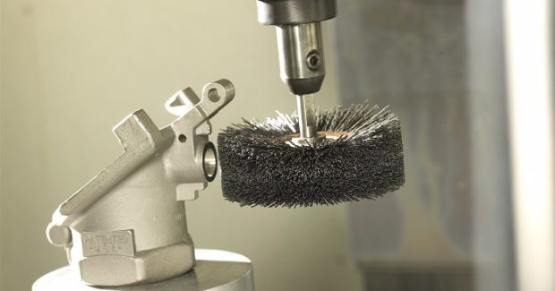
The material type, part geometry and finished part specifications impact the deburring process. Certain materials, such as stainless steel, are more difficult to deburr than cast iron or aluminum. When materials require greater aggression for proper deburring, it is necessary to use longer processing times and abrasives with coarser grits. There is also a higher probability that coolant will be needed to remove heat. A part’s geometry will have a direct impact on media type and configuration required for an automated deburring process. Flat parts require different deburring tools than parts with more than one plane. For example, a flat surface resulting from a milling operation, such as a transmission valve body, is a good fit for disc brush deburring while still fixtured in CNC equipment. Stamped metal parts are well-suited to deburring with abrasive belts or discs on systems with magnetic conveyors. When parts with a more complex geometry have burrs on more than one plane, robots can be used to manipulate the part or the media into different orientations for deburring.
Lastly, selecting the right deburring tool also hinges on the surface finish, edge finish and edge radius specifications. A robust deburring process helps deal with variations that result from the upstream process. Keep in mind that using small media generally leads to limitations in deburring aggression and media life. Therefore, don’t assume that a small part requires a small deburring tool. Because larger media increase system robustness and can reduce the per-part cost, it’s recommended to use the largest deburring tool allowed by the part’s geometry.
STEP NO. 3: SET PROPER OPERATING PARAMETERS
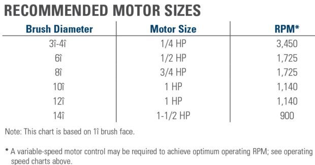
Designing an efficient deburring process also requires selecting proper operating parameters. Part orientation, cycle time and motor power are all important considerations in process design. Burr access is one common challenge in proper system design for automated brush deburring. Burrs that are hidden or masked can’t be removed through proximity to a moving brush filament. Effective design allows brush filaments unimpeded, perpendicular access to the burred edge, so be sure to position edges in a way that minimizes the obstruction or masking of part features. Also, ensure the brush filaments have maximum access to the burr’s root base. This allows the greatest amount of energy at the point where the burr and part are joined. It’s important that the motor has enough power for the job. When a tool has insufficient power, the motor will bog down under the load providing a lower RPM and yield poor results, even if proper media, tool path and remaining operating parameters are in place.
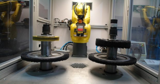
There are available automation technologies that can help optimize the speed and accuracy of the process and reduce media wear. For example, vision and force torque sensing technologies allow a robot to identify part configuration differences and feel the torque being generated by the deburr operation against the parts. A vision system allows parts from different work centers with different geometries to be fed into the cell; the system identifies the part and picks the correct tooling and part program to deburr it. Some vision systems also enable in-process inspection, allowing it to reject an incoming part prior to processing, thereby saving process time and media life. Advancements in force-torque sensors can provide real-time feedback during deburring regarding the amount of force on the part – information that can be used to make in-process adjustments to reduce media wear.
OPTIMIZING DEBURRING
Automated deburring can provide significant benefits, including reduced costs and improved process consistency, in a range of manufacturing applications. Following these steps can help optimize the process for efficiency, quality and productivity.
Subscribe to learn the latest in manufacturing.

Industry News