Adaptive Machining Explained
This primer brings all of the required elements together into a single discussion that explains the correct direction for successful entry into the high-speed /adaptive machining arena.
Posted: November 22, 2019


TOOLING AND WORKPIECE SETUP
Tool selection and tool balance in adaptive machining is important. Though tools are still selected mainly by the part requirements that determine diameter, corner radius, etc., the critical detail to recognize here is that the tool must have the proper relief angle allowing for higher feed rates. Too much relief angle results in a weak cutting edge that will quickly break down and fail. Too little relief angle results in rubbing at high feed rates that causes rapid heat buildup and tool failure. A balance must be found based on the tool and workpiece material being used. One way to increase the potential feed rate is to use a tool with more cutting flutes. These work well on machines that do not have high maximum spindle speeds, but care must be taken to make sure the chips can be successfully evacuated from the cutting flutes. Without improper chip evacuation, the tool will quickly load up and fail, ruining the tool and possibly the workpiece.
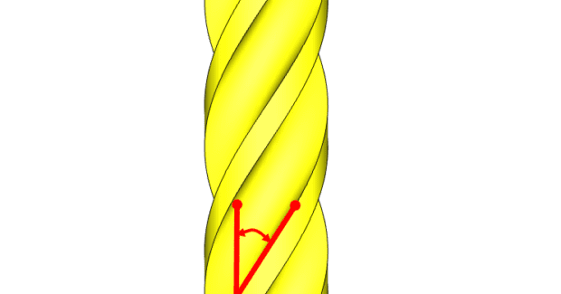
Select tools that are specifically designed to dampen vibration and have a helix angle designed to reduce spindle load and the quick evacuation of chips. Traditional tooling uses lower helix angles from 15 deg to 30 deg. Newer tooling intended for higher feed applications where chip evacuation is important uses helix angles from 30 deg to 60 deg. Balance is very important as spindle speed increases. Vibration in the tool can greatly impact surface finish and rapid tool wear. Every .00039 in (0.01 mm) of runout for a tool can decrease tool life by up to 50 percent. When runout is encountered, a single flute of the tool will be cutting more than the others, causing rapid wear on that flute. Because of this accelerated wear, heat will build up in the tool and workpiece, rapidly breaking down the cutting edges on the tool and possibly work hardening the part. When a tool is engaged in cutting the material, different radial and axial forces exerted on the workpiece and the tool result in vibration and deflection of the workpiece that can reduce the finish being achieved. These forces must be managed by using rigid setups with maximum support to ensure the best possible results from the machining operation.
RADIAL AND AXIAL CHIP THINNING
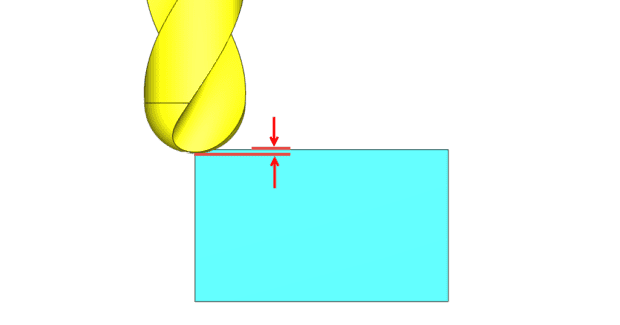
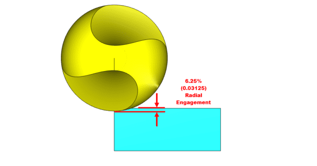
Radial and Axial Chip Thinning are the reduction in thickness of the actual chip being generated based on the tool engagement into the workpiece. Because of this chip thinning, a tool must run at much higher feed rates to maintain the manufacturer’s recommended chip load that reduces wear and increases tool life and surface finish. Axial Chip Thinning occurs when a radius (ball) endmill is used and the stepdown or vertical engagement into the material is less than the radius of the cutter (see Figure 1). When Axial Chip Thinning occurs, the effective diameter of the tool changes: the effective diameter of the tool is much smaller than the actual diameter due to material engagement. This affects the surface finish due to changes in the actual SFM (surface feet per minute) vs. the programmed SFM for the tool.
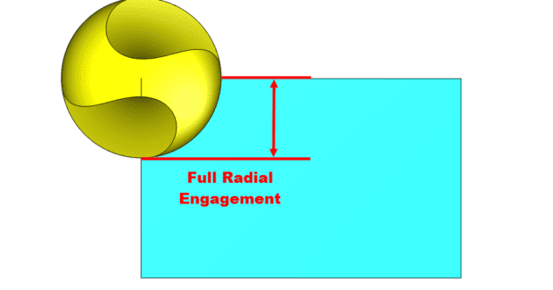
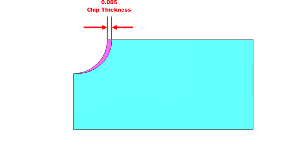
Radial Chip Thinning occurs when cutting with the side of the tool and the stepover value is less than the radius of the cutter (see Figures 2a, 2b). Speed and feed data for the cutting tool will provide the correct SFM and FPT (feed per tooth) values used to determine the proper spindle speed and feed rate to run the cutting tool.
NOTE: For the purposes of this discussion, the effects of deformation of the chip material during the cutting action is excluded. When the thickness of the chip decreases, the tool is no longer cutting at the recommended value. Due to the thinning of the chip, the feed rate can be increased to return the chip load to the desired value. To adjust the feed rate for Radial Chip Thinning, one important factor cannot be ignored: the tool’s engagement into the material.
HOW TO CALCULATE
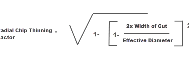
To adjust the feed rate of the path to account for Radial Chip Thinning, you must first find the Radial Chip Thinning Factor. Using this factor, you can then determine either the Unit Per Minute feed rate value or the FPT (feed per tooth) value that should be used to achieve the actual desired chip thickness. The formula for Radial Chip Thinning Factor is:
In this formula, the sequence of calculations to determine the Radial Chip Thinning Factor is:
- Result = Width of Cut times two
- Result = Result divided by Effective Diameter
- Result = One minus Result
- Result = Result squared
- Result = One minus Result
- Result = Square root of the Result
Now the Result contains the Chip Thinning Factor that can be used to calculate both the current chip thickness and the new feed rate to obtain the desired chip thickness. To see the actual chip thickness, the calculation is: Actual Chip Thickness = FPT times the Radial Chip Thinning Factor.
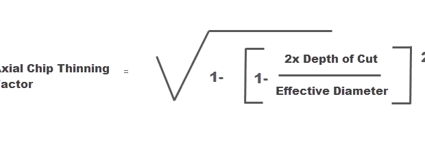
The formula for Axial Chip Thinning Factor is the following:
In this formula, the sequence of calculations to determine the Axial Chip Thinning Factor is:
- Result = Depth of Cut times two
- Result = Result divided by Effective Diameter
- Result = One minus Result
- Result = Result squared
- Result = One minus Result
- Result = Square root of the Result
Now the Result contains the chip thinning factor that can be used to calculate both the current chip thickness and the new feed rate to obtain the desired chip thickness. To see the actual chip thickness, the calculation is: Actual Chip Thickness = FPT times the Axial Chip Thinning Factor.
To find the new Feed Adjustment Factor use: Feed Adjustment Factor = Axial Chip Thinning Factor times the Radial Chip Thinning Factor.
(NOTE: For applications where you are only applying Radial or Axial Chip Thinning and not both, simply use the appropriate Axial/Radial Chip Thinning Factor in place of the Feed Adjustment Factor.)
To find the FPM value, use: New FPM = Starting FPM divided by the Feed Adjustment Factor.
To find the new FPT value that will result in the correct chip thickness use: New FPT = Original Feed Per Tooth divided by the Feed Adjustment Factor.
To review some example calculations and practice using these formulas, go to https://bobcad.com/in-depth-guide-for-adaptive-high-speed-machining-using-cnc-software/.
TOOLPATH STRATEGY
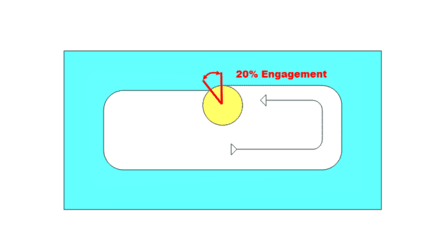
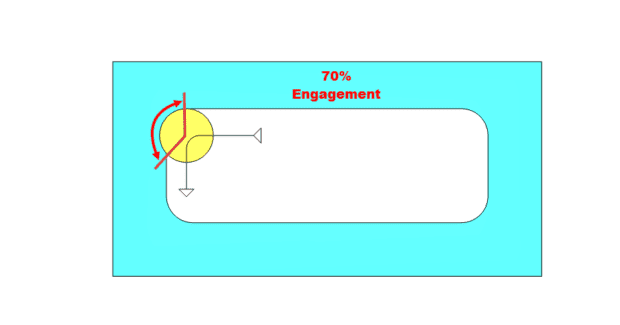
Traditional machining cuts at slower feed rates with varying tool engagement. When cutting a pocket, for example, the engagement of the tool fluctuates as the tool encounters direction changes, such as in a corner. Figure 3 illustrates the engagement while cutting along the wall of this pocket is 20 percent. Because of this engagement, Radial Chip Thinning occurs. The feedrate can be increased to reduce the cycle time, but as the tool continues to cut into the corner, the engagement of the tool is greatly increased. As the engagement of the tool into the workpiece increases, the pressure exerted on the tool also increases and leads to chatter that causes poor surface finish. Another side effect of the increased tool engagement is the increase of heat being generated. As a tool spins and the flutes engage in material the cutting action generates heat. During the rotation when the tool is not engaged, the chip is expelled and the tool cools as it rotates around until it contacts the material again. This cooling duration is longer or shorter depending on the engagement of the tool into the material.
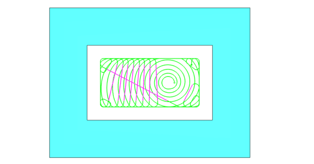
When trying to cut at high speeds, this variation in tool engagement limits what can be done to reduce cycle time. To run tools faster in the material, an altogether different toolpath strategy is necessary: The adaptive toolpath gently moves the tool into and out of the cut using a radius motion that minimizes the impact on the tool and allows the machine to achieve faster motion by eliminating sudden direction changes that force the machine tool to slow down to maintain accuracy (see Figure 4).
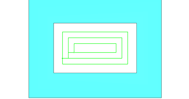
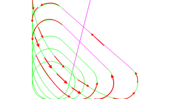
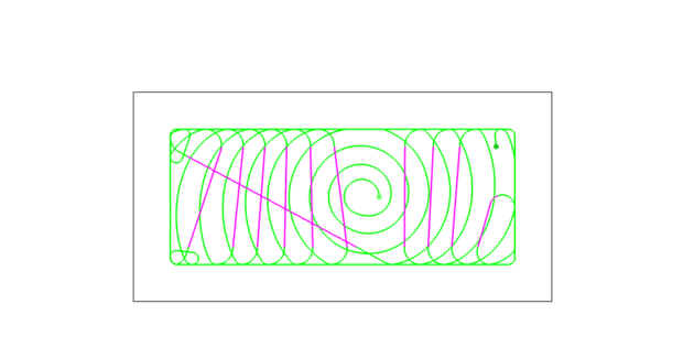
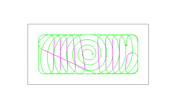
Controlling the size of the curving motion is important because the larger the tool, the larger this radius must be to ensure tool engagement amount is maintained. The curving motion is controlled in our Adaptive software strategies using the Minimum Curvature Radius value. In Figure 5, notice how the curvature of the path changes with this value in the following images.
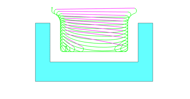
When using our One Way machining strategy, the adaptive path includes link back moves that perform a “Micro Lift” if the distance is greater than 5X the tool diameter. In Figure 6, this Micro Lift move is displayed in the pink color. Link back moves are used to reposition the tool for the next pass across the material. Our system will apply the Maximum Defined Cutting Feedrate value to these moves in the NC program so the machine can run at a much higher feed rate for this motion and further reduce cycle time reduction.
References
- http://www.mmsonline.com/articles/the-high-feed-high-reliability-process
- http://www.mmsonline.com/articles/high-speed-machining-without-the-speed
- http://www.mmsonline.com/articles/10-tips-for-titanium
- http://www.mmsonline.com/articles/high-speed-machining-without-the-fast-spindle
- http://www.mmsonline.com/articles/a-new-milling-101-milling-forces-and-formulas
- http://www.moldmakingtechnology.com/articles/rough-milling-speed-vs-power
- https://www.makino.com/about/news/hsm-research—on-the-edge-of-technology/145/
- http://www.ingersoll-imc.com/en/products/ingersoll_cat-009_technical.pdf
- http://www.cimindustry.com/article/tooling/high-speed–machining-defined
Subscribe to learn the latest in manufacturing.
Industry News