How to Avoid Bending Moment
Equal cutting forces affect the spindle in different ways with different tools. Unless/until machine tool builders or tool simulation software integrate bending moment limits, it’s up to you to use your best judgment. BIG DAISHOWA’s Jack Kerlin explains in the second installation of a two-part series.
Posted: July 30, 2020


DEPTH OF CUT COLUMN
BY JACK KERLIN
Last month we defined bending moment and the damaging affect it can have on your spindle and tools. This month I’ll explain how to avoid the damage.
Besides eyes and ears, many machinists rely on a load monitor to assess how taxing an operation is on the machine. More importantly, it may help to predict a costly crash before it happens. Modern CNC machine tools have load meters built into the control as one of the ever-increasing ways that the machine can “speak” to the operator. How this load is displayed varies from machine to machine, but typically what’s shown is a percentage ranging from 0% up to 200% or even 300%. This reading acts as a linear scale of some manufacturer-determined maximum load. In any case, load meters merely measure electrical power consumption of the spindle motor and the other servomotors responsible for each positional axis.
Why does the machine even allow the operator to surpass 100% load? The short answer is that electric motors can pull more power than what they’re rated for. Essentially, it has become an industry standard to define 100% (whatever that value may be for the servomotor model) as the power consumption level that is safe for continuous and constant operation. Obviously, however, the power drawn by the machine tool is anything but continuous or constant.
In reality, the rated power advertised on the side of each individual motor is fairly modest compared to its true maximum capability. Over 100% load is momentarily required just to kickstart the motor from standstill. And in a production-minded industry like ours, it is understandable that there is a desire to exceed this limit to reduce cycle times, if possible. Furthermore, certain jobs are only possible through heavy material removal, which are more power-intensive than what the motor can appear to handle. When it comes to machining, it is acceptable and even encouraged to push the motors past 100% from time to time.
Consequently, it is crucial for an operator to understand the limits of his or her machine. Unless you’re a hobbyist, you will most likely be working with machines equipped with 3-phase servomotors. These will have a maximum continuous power rating stamped on the side. It’s important to differentiate between this and max “peak” power rating, which, as you might have guessed, represents 200% or 300% load.
Generally, running at anything over 100% is only recommended for short intervals. Avoid the peak power rating if possible unless you’re willing to risk damaging the machine. This damage could range from frying electrical components after long cycle times to physical stalling of the spindle or feed axes mid-cut (it happens to the best of us). You may already know this, but the point is to illustrate how what’s going on behind the scenes factors into what the machine is communicating.
Now that you have a basic understanding of the handy-dandy load monitor, it is clear that the machine only understands overloading in terms of electrical power consumption in the motor(s). It will blindly follow the code it is fed until it crashes or the program ends, or both. In fact, it’s also blind to its absolute position until you “home” it out.
Detecting Overload
Most, if not all, of what the machine knows about the work envelope comes from user input. For this reason, a machine tool will only ever be as good as its operator. In addition, machine tool builders are only responsible for the systems up until gage line, at which point the baton is passed off to the tool and toolholder industries. There’s no way for a machine to account for the tool, much less any obligation for tool builders to incorporate a cutting force monitoring system into the machine. The same goes for cutting simulation software. The control’s line of questioning begins at “how long and wide is the tool?” and usually ends there.
This begs the question: How does it detect overloading in terms of cutting forces and the resultant bending moment that could deform or destroy the spindle or tool? The answer is that few machines have force gages or sensors built in, so the responsibility falls on the operator to anticipate and prevent this sort of damage. This doesn’t often happen.
Even if you have one of the few machines with those features, they don’t consider cutting tool length. These sensors measure raw cutting forces, so 500 pounds of radial cutting force at the end of a 10-inch-long shell mill will read the same as 500 pounds of radial cutting force at the end of a 3-inch-long shell mill. The problem is that we all know that the impact on the spindle is vastly different in these two scenarios, power consumption aside; and the servomotor(s) driving this operation are unaware of this difference by design. This disconnect between tool and machine is what leads us to the concept of bending moment.
Hypothetically speaking, it’s entirely possible to damage the spindle without exceeding 100% on the load meter. In fact, it’s possible to damage the spindle without exceeding 50% on the load meter.
Just because a cutting operation doesn’t overload the machine servomotors doesn’t necessarily mean that the forces involved won’t break the tool or irreparably damage the spindle. Not only is it difficult to monitor the dynamic cutting forces while machining, but the length of the tool will act as a force multiplier. The machine will never account for this variable.
Bending moment is the reason cutting load meters are only reliable when working axially with respect to the spindle (drilling, rough boring, plunge milling, etc.), or very short and rigid radial cutting (stubby face milling).
In any other case, the indicated load is misleading at best and potentially catastrophic for the tool or machine at worst. The higher the radial load on the spindle or the longer the tool, the more you should be cautious about load information the machine is communicating. Use your best judgment; if the load monitor says 100% but the tool is already bending like a wet noodle, you may want to rethink your strategy. Remember: The machinist is still the most important part of the machine tool. Your brain is a biological computer that controls everything that happens; the machine isn’t telling itself what to do.
Combat Bending Moment
At this point you may be wondering how you can best combat the bending moment problem; but the truth is, it’s not always possible. There will always be long-reach applications, whether it is because of workpiece geometry or machine tool space limitations. It also can be hard to predict when your spindle approaches its threshold, much less realize that it’s happening. Neither the operator nor the machine is actively monitoring bending moment.
The first rule of thumb, which may seem like common sense, is to avoid the combination of long tool/high radial load. Skilled machinists strive to find the Goldilocks zone: not too long; not too short; just right. The goal is to ensure you’ve taken every possible precaution so the chances of this happening are low from the start. Sustained vibration should also.
Once you’ve picked proper tooling for the job, it’s key to follow manufacturer cutting parameters and adjust if necessary. This is empirical data that was collected during testing, so it’s grounded in practical use. Especially important is stock allowance, so that radial force doesn’t overpower axial in long-reach applications. This is a common issue in finish boring and the main cause behind chatter.
Need For Limits
Now this may all be well and good, but wouldn’t it be much more helpful to have some form of quantitative limits to at least make some effort to abide by? A few manufacturers have ventured into publishing bending moment limits for different spindle tapers, though the information is often presented in such a way to shed the best light on their particular product.
There also doesn’t seem to be a consensus on how to define “max” bending moment limit. Some say it’s when complete dual contact is lost, while others say it is when there’s a certain amount of deflection.
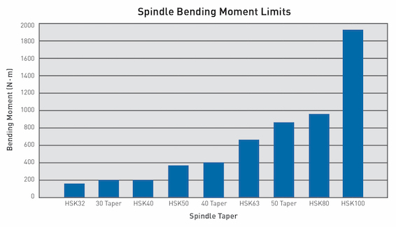
The deflection limit method is used in the chart comparing spindle bending moment limits, concentrating on a gage length and specifying a deflection limit. Clearly CAT40 is outmatched by HSK63 (two commonly compared spindle interfaces) due to the higher clamping force and the fact that HSK is dual contact by default. However, with BIG-PLUS dual contact, the bending moment limits would be very similar, if not the same.
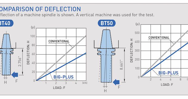
Unfortunately, BIG-PLUS isn’t an international standard, so this taper connection isn’t included in the guidelines. It can also be difficult to quantify a bending moment limit based on deflection, because dual contact is more influential with certain tool geometries over others. Nevertheless, it’s impossible to deny the advantage in rigidity BIG-PLUS provides over traditional steep-taper tooling, as many can attest.
Having said that, the best spindle taper option will depend on your situation; there’s no be-all and end-all solution just as there’s no be-all and end-all toolholder type. HSK may provide more clamping force, rigidity, and higher speeds than steep taper, but this is at the expense of cutting torque. Capto may do the same, but at the expense of manufacturing cost. An entire book can be written on the subject, but the point is: Dual-contact tooling offers additional protection against dangerous bending moments and spindle fretting (in addition to other benefits).
So, if you don’t already have a dual-contact interface, consider making the switch. And if your pocketbook disagrees, consider BIG-PLUS specifically. Converting from standard CAT40 to BIG-PLUS CAT40 technically allows you to use your standard tooling. In the meantime, you can buy BIG-PLUS tooling as your budget allows.
Again, most of these solutions amount to little more than qualitative precautions. You’re probably already using the shortest possible tools with manufacturer-approved parameters, but it’s critical to stress these points because they’re the easiest and least time-consuming. And to be honest, you probably won’t have time for anything else on the shop floor. I would be out of touch if I expected you to look at your spindle taper bending moment limit, gage length for each tool, monitor the load, and make a calculation in your head at the same time. So, the best defense is still to avoid these situations. Or if there’s no way around a long-reach or heavy roughing operation, being extra cautious.
Until the day comes when machine tool builders or tool simulation software can successfully integrate bending moment limits, it’s up to you to use your best judgment. It may one day be possible to integrate active FEA analysis and predict when the tools and toolholders will fail. But for now, simply recognizing that equal cutting forces affect the spindle in different ways with different tools is the important first step.
Subscribe to learn the latest in manufacturing.

Industry News