Design Is Destiny If You Want To Optimize Beveling
Even the most sophisticated nesting software won’t eliminate the need to manually finish an edge if the job’s not thought through from start to finish. Follow these three best practices to minimize wasted time and material.
Posted: January 17, 2021


DIGITAL BY DESIGN COLUMN
BY PAUL IKEDA
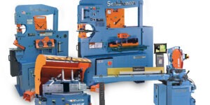
Bevels are edge cuts typically used to prepare steel plate parts for welding, but are used in a variety of applications – each of which presents its own set of challenges. In addition, thermal cutting, abrasive cutting, and machining each present a different set of considerations when performing bevel cuts on plate, tube, composites, and so on. Regardless of how simple or complex the part is, the process requires experience and a thorough understanding of machine and material.
Fabricators have long relied on CNC machines and nesting software to fine- tune and automate beveling. Even so, a bevel’s geometry and nesting challenges have long been a process of trial and error. Despite wasted time and a high scrap rate, part are still likely to require manual cleanup. Here are three ways to minimize wasted time and material.
First, Know Your Machine
Most pitfalls can be avoided during the design phase, so the first step is to have a good grasp of the project’s feasibility. One common error is assuming your machine can cut every potential bevel.
Not so. Just because something is modeled in 3D doesn’t mean your shop can fabricate it. A draftsman can model almost any shape, but it doesn’t guarantee the programmer or operator can cut it. To avoid this sticky situation, design engineers should consider three things.
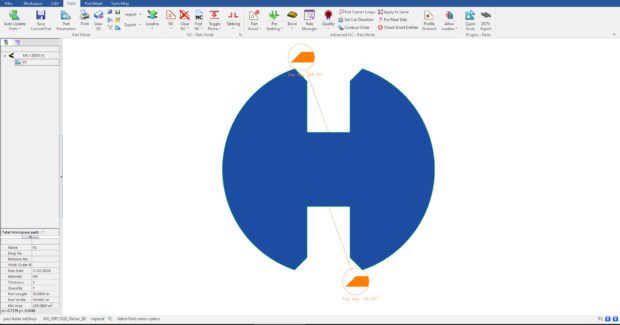
Complex bevel corners. Can the machine reach all the surfaces of the bevel cut without the part prematurely separating from the sheet? Also, if the machine has to spend too much time in the same area, there will be heat distortion issues.
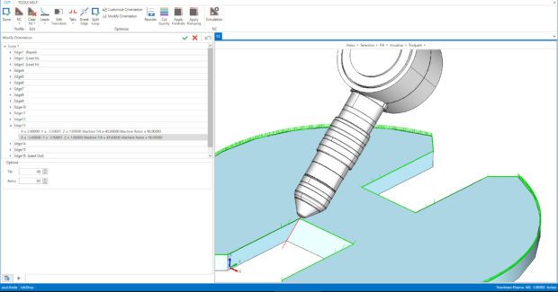
Variable bevels. Can your machine change its tilt and rotor while cutting? If not, certain bevels could cause bottlenecks in production by greatly reducing cutting speed.
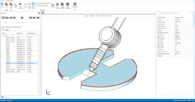
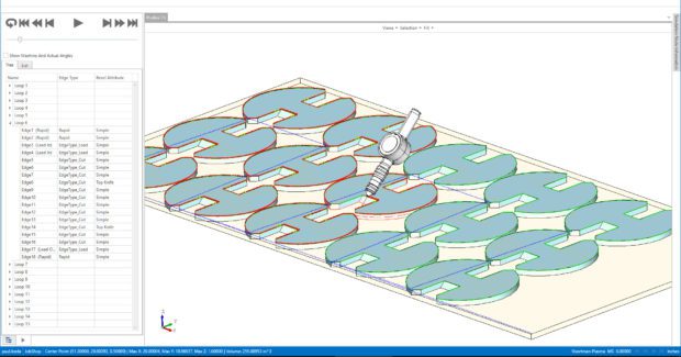
Maximum tilt angle. What is the maximum combined angle for a bevel or corner with bevels? Beyond the maximum angle, the machine may error or require a mechanical reset maneuver to continue, resulting in delays and scrapped parts. A 3D simulation of the cutting process allows engineers to digitally evaluate bevel feasibility during design.
Second, Maximize Your Resources
Maximizing throughput, and thus profitability, is all about improving performance in five areas: machine, material, manpower, motion, and management. Design-for-manufacturability principles affect each area.
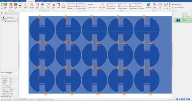
Material utilization. Transitioning from one bevel to another by using corner loop transitions requires additional nesting clearance, which produces more scrap. Consider loop size and shape during programming or use swarfing (cutting and tilting while moving) if your machine supports it. You can also use nesting software that offers a no-corner-loops option when generating NC code.
Motion optimization. Although swarfing can improve cycle time, minimize pierces, and increase material utilization, it may reduce edge quality and add testing time. Depending on the part, it may not be the best bevel-cutting technique to use in all cases.
Manpower efficiency. The designer and programmer may decide not to include a full bevel (or possibly any bevels) in the cutting process, planning instead to hand-cut or grind the required chamfers as a separate operation. However, replacing manual labor with machine-cut bevels can save time and generate consistent-quality work.
Management of data. Most major CAD systems support a concept that allows different configurations or multiple versions of the same part. In the early stages of the design process, it’s important to consider the manufacturing steps needed to produce a part. A part file may have a bevel and non-bevel version. Rather than memorize your part library, use CAD tools like configurations or revisions to streamline production workflow and data storage.
Manufacturing automation. Design parts so there’s little room for error and the need for human intervention is limited. If the part is well-designed, the programmer or programming software can quickly and/or automatically generate a toolpath to drive the cutting machinery and produce ready-to-ship parts.
While it may not always be possible to cut a part with just one machine, take time to consider how to streamline your current process. It may be useful for the designer and plant manager to walk through the steps of a job from start to finish.
Third, Focus on the Part’s Purpose
Flexibility in the production process is very important. Your programmer should have the confidence and ability to make changes on the fly. Being able to add, edit or remove bevel features to prepare the part for each step in the manufacturing process has become a respected and vital skill. Make sure your production team is properly aligned to make these changes so a small hiccup doesn’t turn into hours of downtime.
Although part modelling or programming approaches may vary, the most important thing to consider is what the customer will do with the finished product. It may be a heavy structural part that requires some weld preparation. It could be aesthetic in nature or a critical exterior component that must meet high tolerance requirements. In either case, it’s important to ensure the design works all the way down to the finished part so that it serves its purpose. Successful teams waste fewer resources, and thus increase profitability, by keeping intent in mind.
Feasibility, resource management and flexibility all play an important role in designing beveled parts. By adopting these design considerations, viewing your machine processes holistically and knowing the process backward and forward, design decisions can be made in ways that reduce cost and improve efficiency.
Subscribe to learn the latest in manufacturing.

Industry News