Accuracy of Feed Axes (Part Two)
In the total error budget of a machine tool, the positioning error values of the feed axes play a critical role. The conclusion of this two-part series examines the influence of the temperature distribution along the ballscrew.
Posted: March 20, 2008


INFLUENCE OF THE TEMPERATURE DISTRIBUTION ALONG THE BALLSCREW
Apart from the ratio of bearing stiffness, the position of the thermal zero point depends particularly on the distribution of temperature along the ballscrew.
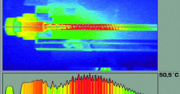
Figure 12 shows a thermographic snapshot of a ballscrew drive after several hours of reciprocating traverse between two points at a distance of 150 mm. As the thermograph shows, even after several hours the temperature increase remains almost exclusively in the area of ball nut traverse. The temperature of the ballscrew and therefore the thermal expansion is very local.
Because the bearings of the ballscrew can provide at best only an evenly distributed mechanical tension and ensure constant expansion along the ballscrew, they cannot compensate the expansion resulting from local temperature changes.
A simple calculation shows this clearly (Figure 13). On a 1 m long ball screw with a fixed bearing at one end, a local temperature increase of 10 K as indicated by the red curve in Figure 13 (left) would result in a positioning error as indicated by the green curve in Figure 13 (right).
A fixed/fixed bearing configuration with rigidity of 700 N/μm results in an error curve as indicated by the blue curve. As a result of the forces exercised by the bearing, the ballscrew is compressed in the ends where the temperature is not increased.
The area of the ballscrew near its midpoint expands due to the temperature increase at almost the same rate as with the fixed/floating configuration. At 22 μm, the maximum positioning error from the fixed/fixed configuration is roughly 2/3 of the error that occurs from the fixed/floating configuration.
COUNTER MEASURES
The test results discussed up to this point show that the thermal expansion of the ballscrew as a result of friction in the bearings and particularly in the ball nut results in significant positioning error if the axis is controlled in a semiclosed loop.
Besides the use of linear encoders, countermeasures aimed at avoiding this error include coolant-conducting hollow ballscrews and purely electronic compensation in the control software.
COOLED BALLSCREWS
The circulation of the coolant requires a hole in the ball screw and, for rotating ballscrews, rotating bushings near the screw bearings. Apart from the sealing problems, the hole reduces the ballscrew’s mechanical rigidity in its already weak axial direction. The greatest problem, however, is a sufficiently accurately temperature control of the coolant. A 1 deg C change in temperature changes the length of a 1 m long ballscrew by 11 μm.
In light of the considerable amount of heat to be removed it is not an easy task to maintain a temperature stability of < 1 K. This is particularly so when the spindle or its bearings are cooled with the same system. In such a case, the required cooling capacity can easily lie in the kilowatt range. The temperature constancy of existing spindle chillers is usually significantly worse than 1 K. It is therefore often not possible to use them to control the temperature of the ballscrew.
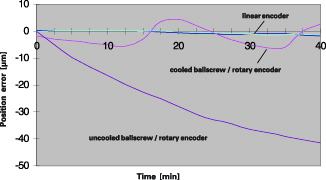
Switching controllers are often used in the chillers to reduce cost. Since each switching operation is triggered by a violation of temperature limits, the individual switching operation can be considered to be an expansion of the cooled ballscrew and therefore an axis positioning error. Figure 14 shows the result of a positioning test on a vertical machining center with liquid-cooled ballscrews in fixed/floating bearings.
During the test, the axis was moved slowly at 2.5 m/min between two points at a distance of 500 mm. The maximum traverse range was 800 mm. The position drift of the position farther away from the fixed bearing was recorded. The switching of the chiller is plainly visible. Its hysteresis was 1 K.
Compared with the noncooled semi-closed loop design, the absolute position drift was significantly reduced. However, the switch operations produce relatively quick changes in position, which have a stronger effect during the machining of workpieces with short machining times than the slow position drift evident in the noncooled semi-closed loop design.
SOFTWARE COMPENSATION
Research is underway on compensation of thermal deformation with the aid of analytic models, neural networks and empirical equations. However, the main focus of these studies is in the deformation of the machine tool structure as a result of internal and external sources of heat. There is little interest in investigation into compensation of axis drift.
As a whole, the possibilities of such software compensation are frequently overestimated in today’s general atmosphere of enthusiasm for software capabilities. Successful compensation in the laboratory is usually achieved only after elaborate special adjustments on the test machine. It is usually not possible to apply such methods to machines from series production without time-consuming adjustment of the individual machines.
The example of the feed axis shows the variations on input parameters to be considered. To compensate the expansion of the ball screw, its temperature must be known with respect to its position, since the local temperature depends on the traversing program. Direct temperature measurement of the rotating ballscrew, however, is very difficult. Machine tool builders therefore often attempt to calculate the temperature distribution.
This is theoretically possible if a heat analysis can be prepared for individual sections of the ballscrew. The heat in such a section is generated by friction in the ball nut through thermal conductance along the ballscrew, and through heat exchange with the environment.
The friction of the ball nut depends almost proportionately on the preload of the ball nut and, in a complex manner, from the type, quantity and temperature of the lubricant. The preload of the ball nut normally changes by ±10 to 20 percent over its traverse range in a manner depending on the individual ballscrew. In the course of the first six months, the mean preload typically decreases to 50 percent of its individual value.
Due to the complex interaction of static forces at play on the ball screw, certain jamming effects and an associated increase in friction are unavoidable. Even these few of a long list of examples show that the calculation of the actual frictional heat presents formidable problems.
Calculating the heat dissipation is similarly difficult because it depends strongly on largely unknown ambient conditions. Even the temperature of the air surrounding the ballscrew is normally unknown, although it plays a decisive role in any calculation of heat dissipation.
On the whole it seems certain that, even in the relatively simple case of a fixed/floating bearing, software compensation of ballscrew expansion without additional temperature sensors has little chance of success. In the case of fixed/fixed and fixed/preloaded bearing one must also take into account the bearing rigidity and the preload-dependent friction in the bearings. These factors make compensation even more difficult.
COMPARISON OF POSITIONING ERROR WITH OTHER TYPES OF ERROR
After this discussion of temperature-dependent positioning error of feed drives, it remains to classify these types of error with the other types of static and quasistatic error in the total error budget of the tested machining centers. The frame deformation resulting from the heat generated by the spindle was examined on all three machines in accordance with ISO/DIS 230- 3.
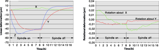
After several hours of operation with a maximum spindle speed of 6,000 rpm, the first machining center showed a linear deformation of {x: 5 μm, y: 60 μm, z: 15 μm}. The rotational deformation was at most {a: 40 μm/m, b: 70 μm/m}. The deformation of the second machining center is shown in Figure 15.
Under the same conditions, also with 6,000 rpm, it shows a maximum linear deformation of {x: 5 μm, y: 45 μm, z: 55 μm}. The rotational deformation reached a maximum of {a: 25 μm/m, b: 10 μm/m}. The third machine was equipped with a high-speed spindle and jacket cooling. At 12,000 rpm it showed linear deformations of {x: 5 μm, y: 5 μm, z: 40 μm} and rotational deformations of max. {a: 20 μm/m, b: 30 μm/m}.
The measured axis drift values attain at least the same magnitude as the structural deformation. Particularly on spindles with fixed/floating bearings, or machines with effective cooling of the spindle, the positioning error of the feed axes driven in a semi-closed loop is significantly greater than the measured structural deformation. A comparison with the usual geometric error leads to similar results.
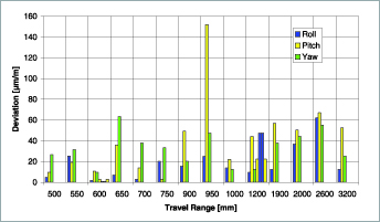
If one observes the pitch, roll and yaw error of the feed axes of 16 different NC machines one sees that these types of error usually lie in the range of 10 to 50 μm/m (Figure 16). The positioning error is found by multiplying these values by the respective Abbe distance. The error does not attain the values of the feed axis until over 1 meter traverse.
CONCLUSION
The primary problem involved with position measurement using rotary encoder and ballscrew is the thermal expansion of the ballscrew.
With typical time constants of one to two hours, thermal expansion causes positioning error in the magnitude of 0.1 mm, depending on the nature of the part program. This positioning error therefore outweighs the thermally induced structural deformation and geometric error of machining centers.
After every new part program the ballscrew requires approx. one hour to attain a thermally stable condition. This also applies for interruptions in machining. A rule of thumb for thermal expansion is that, over the entire length of a cold ball screw 1 meter in length, the ballscrew grows by approx. 0.5 to 1 μm after every double stroke. This expansion accumulates within the time constant.
As requirements for machine tool accuracy and velocity increase, the role of linear encoders for position measurement grows increasingly important. This should be taken into consideration when deciding on the proper feedback system design.
Literature
1) Schröder, Wilhelm, “Fine Positioning with Kugelgewindetrieben,” Progress Report VDI Row 1 NR. 277, Düsseldorf; VDI Verlag 1997.
2) VDW-Bericht 0153, “Investigation from Waelzfuehrungen to the Improvement of the Static and Dynamic Behavior of Machine Tools.”
3) Weule, Hartmut, Rosum, Jens, “Optimization of the Friction Behavior of Ballscrew Drives Through WC/C Coated Roller Bodies,” Production Engineering, Vol. 1/1 (1993).
4) Golz, Hans Ulrich, “Analysis, Concept and Optimization of the Operational Behavior of Kugelgewindetrieben,” University of Karlsruhe thesis, 1990.
5) Schmitt, Thomas, “Model of the Heat Transfer Procedures in the Mechanical Structure of CNC Steered Feed Systems,” Shaker publishing house, 1996.
6) A. Frank, F. Ruech, “Position Measurement in CNC Machines . . .,” Lamdamap Conference, Newcastle 1999.
Dr. Jan Braasch is the manager of linear encoder development at Dr. Johannes Heidenhain Gmbh, Dr.-Johannes-Heidenhain-Straße 5, 83301 Traunreut, Germany, (0 86 69) 31-0, Fax: (0 86 69) 3 86 09, www.heidenhain.de.
Subscribe to learn the latest in manufacturing.

Industry News