MORE POWER TO YOU:
ENSURING THE QUALITY OF WIND TURBINE PARTS
Advanced technologies from Bosch Rexroth, Carl Zeiss, Meta Vision Systems and MAG Americas are being used to maintain low variation process signatures, measure difficult-to-access precision structures, and make sure every component in wind technology is of the highest quality.
Posted: April 8, 2010


In the fast growing market for wind power systems, quality assurance according to international industrial standards has become an important issue. Wind power plants are no longer a niche playground for environmental proponents, but a serious business where cost efficiency, life cycle costs, reliability and availability of the components must be considered.
THE TOWER
To a great extent, wind energy still depends on traditional manufacturing techniques. Welding, for example, is vitally important for creating the massive towers used in these wind power systems. One of the leaders in creating welding solutions for the energy industry is machine builder AMET Inc. (Rexburg, ID). Since 1989, AMET has been an innovator in developing and integrating advanced welding systems to meet a wide range of demanding needs.
To help insure the process quality for a new generation of custom welding systems for the wind energy industry, AMET needed linear motion and assembly technology the capabilities to meet the unique welding needs of wind turbine builders.
The design of welding equipment, which drives the role of linear motion technologies, is largely dictated by the techniques required to create wind turbine towers that can be around 90 m high (close to 300 ft). Typically, a flat metal plate is rolled into a cylindrical shape called a ?can.? The most common size of the can is approximately 9 ft long by 8 ft to 15 ft diameter. This can rotated while the welding machine, staying more or less stationary, performs circumferential welding across the entire diameter.
Longitudinal welds are also required.
Wind tower welding systems generally operate both inside and outside of the can at different times; the welding equipment is usually suspended from a guide rail for outside welding. In each case, while the bulk of the welding equipment remains stationary during a weld, the weld head constantly moves small distances along at least two (sometimes three) axes, both along and across the seam.
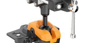
A linear control actuator mounted at the end of a horizontal arm determines the motion of the weld head. The goal here was to create a cost effective, dependable welding system that could perform accurate longitudinal and circumferential submerged arc welding. The design, including the linear motion for weld head control, would ideally be straightforward and simple, so the welding system could enter an increasingly competitive market as quickly as possible.
One of the most important challenges, however, was to assure smooth and precise (within 1/100th in) control of the weld head, to avoid improper welds that would need to be redone and ultimately result in wasted time and materials. This precise control also had to be maintained within a very demanding environment. ?The tremendous amount of particulates generated by this form of welding, especially flux dust, can really cause problems for the machine?s finer controls, particularly with systems such as linear actuators,? explains Craig Dees, the engineering manager of AMET. ?We needed to be sure that the linear motion components would stand up to this harsh welding environment, especially inside the can.?
In addition to good protection against flux particulates, which can cut into uptime, the linear motion elements had to offer good strength to handle dynamic loads in excess of 20,000 N with light weight and compact size. Yet another challenge was to support smooth weld head acceleration of up to 3 m per second squared (3 m/s2), for a travel speed of 1.5 m per minute.
To meet these needs, AMET turned to Northwest Motion, Inc. (Issaquah, WA), a distributor of Bosch Rexroth linear motion products. AMET had already used Rexroth CKK Compact Modules in a number of other custom welding applications, and Northwest Motion recommended these for the desired strength-to-weight ratio. On the standard platform for the welding system, Rexroth precision-ground, hardened steel guide rails were used to carry the suspended weld head for outside welding.
AMET generally specifies two (occasionally three, for even more precision) CKK 20-145 linear actuators for their custom welding systems, in 490 mm and 590 mm standard lengths. Some of these systems use CKK 15-110 actuators. As Dees points out, ?One of the features that we noticed right away as a potential advantage for these actuators is that their compact dual-rail system features a sealed rolling strip.?
That?s important because many linear actuators use fabric or rubberized bellows to keep the rolling strip clean, but the seal on this system keeps the module protected from the pitting that?s caused in other actuators by the particulates being generated from the welding process. The compact design, light in weight but durable and strong, made the assembly of the machine smoother and easier. ?Other linear motion systems couldn?t give us the reliability and protection against contamination and pitting that these actuators do,? notes Dees.
There?s more. Between the dual carriage option and the dual rail design integrated into the rigid aluminum frame, this module gives the can welding system a guideway with a dynamic load capacity of up to 61,000 N with excellent stability. The actuator resists impact and stress, as well as sparks and contaminants, further increasing uptime.
The linear modules contribute to more compact welding systems with a high load rating and an overall strength that?s especially valuable if the weld head strikes the side of the can. By keeping out particulates, the sealed rolling strip maximizes reliability and uptime while reducing maintenance.
Wind turbine manufacturers benefit from a welding system design that?s ideally suited to the most common tower section sizes, including the larger sizes needed to create wind turbine support towers more than 75 m high. These economical custom welding systems not only make high quality welds that look good, the systems themselves are as attractive as they are reliable and dependable.
These actuators enable AMET to build the welding platform better and faster because they are complete, prepackaged systems, with dual ball rails and a ball screw drive integrated into the module. The simplified design saves space and removes the costs and effort of machining, assembly, bearing alignment and other application engineering tasks. ?Because the modules are precision-machined at the factory, we don?t need to do any extra work ourselves,? says Dees. ?They?re ready to run as soon we get them, so we just add them to the system.?
With Northwest Motion providing rapid delivery, superior parts availability and competitive pricing to AMET, ?getting quality linear motion for less cost allows us to pass the cost savings along to the customer, and give them the welding quality they want at an attractive price,? adds Dees. All of this cuts two weeks from the cycle time it takes to build the welding system, which usually runs about 12 weeks per machine. Most importantly, these modules, as controlled by proprietary AMET systems, help ensure high process quality and dependable performance in the welding of many wind tower applications.
Because the thickness of the steel plates that form the base of a wind tower can be 50 mm or more, while the middle section is fabricated from lighter gauge metal and near the top, the steel is thinner still. This means welding these various gauges requires different procedures. The base is typically prepared with a U joint profile where welding takes place in several passes. The middle section requires a V-type joint that is welded in one or two passes. Steel at the top is welded with a simple butt joint preparation.
To maintain process quality and further increase the automation and speed of these welding procedures used on wind towers and other structures containing metal of different thickness, the DLS200 scanning-spot laser sensor from Meta Vision Systems (Eynsham, Oxfordshire, UK) has a fully programmable scan configuration that uses a wide scan for the U and V joints, but a narrow scan with high resolution is used for the smaller butt joints.
Another exclusive feature of this sensor is that the stripe produced by the normal laser scan can be shrunk to a spot, which is useful for welding cap passes where the edges of the weld preparation may have melted away. At the touch of a button, the sensor can project the spot to measure and control the height of the welding head. At the same time, the machine operator can use the laser spot as a guide for manually controlling the horizontal position of the welding head.
These sensors are used to assist the automated welding of wind towers at test sites. Wind tower manufacturers say that the main benefit of using the sensor to provide automatic control of the welding process is improved quality. Defects are reduced, which translates into large savings, especially considering the time and cost of repairing root weld defects in thicker material.
Meta managing director Bob Beattie says, ?We originally developed this sensor for multipass welding of very thick walled components, such as nuclear vessels. But since the new sensor has a smaller depth of field with consequently higher resolution, this makes it ideal for the combination of large, medium and small weld joints that are common in wind tower fabrication.?
THE WIND TURBINE GEAR BOX
Gear boxes are a major part of all wind turbines. The quality requirements are high: as the wind blows in gusts, a backlash-free operation is indispensable to ensure a long and beneficial lifespan of the system. Mechanical efficiency is directly related to economic efficiency. Noise reduction in the gear box is important to ensure the public acceptance of wind turbines and the industry has to follow these requirements. Not many manufacturers are able to produce such large gear boxes (and with the off-shore systems, the sizes are even larger), and now they have to deal with serial production, having many unknown requirements for quality in very large dimensions.
Gears (ring-gear, sun gear, and planet), bearings, and housings have to be produced with tolerances down to 1/100 mm ? on components with 4 m or more in diameter. It is no longer possible to machine these parts without specific measures to ensure the quality because the parts are too expensive to produce rejects. So a reliable control of the manufacturing process must be installed, in real time, during machining.
Coordinate measuring machines play a vital role in ensuring the accuracy and quality of components used in wind turbine components. For example, Carl Zeiss IMT (Maple Grove, MN) developed the MMZ series of machine measuring centers that are tailored for the precise, economical measuring of large parts. MMZs are used in the wind energy industry all over the world, including North America, South Korea, China, India, and several European countries. These systems help the wind energy industry to ensure the growing quality standards that must be achieved today and in the future.
These systems include the MMZ G, which has established applications in quality assurance for gearboxes and other parts for large wind turbines. The larger MMZ E and B gantry-type machines measure composite parts and machined parts with standard accuracies. The even larger MMZ T bridge-type machine uses an integrated steel table for the high accuracy ?mid-size? class (up to 2000 mm x 3000 mm x 1600 mm). And the MMZ-G measures very large precision component sizes up to X = 2000 mm, Y = 3000 mm, and Z = 2000 mm. It also handles gears and bearings up to 5 m in diameter and housings or other machined parts up to 11 m in length, 5m in width and 3.5 m in height.
The MMZ G machine is designed as a welded steel construction; everything is calculated according to the finite elements method. The machine moves on linear guideways, is driven by a ball screw spindle, is rigid and robust as a machine tool, and has no air consumption. The machine can be equipped with floor integrated rotary tables, holding up to 12,000 kg. Gears can be measured with or without the rotary table. For some helical or bevel gears, a rotary table would help to get full access to gear flanks.
Using standard Calypso® software, all geometric dimensions can be easily measured, including form and position tolerances. Adding Gear-Pro software allows for the measuring of internal and external gears, straight or helical. Bevel gears and worms are measurable. With the Vast® probe head, the machine not only takes single points, but is optimized for surface scanning. Navigator® technology scans with long, flexible styli at high speed rates without losing accuracy. The probe head can hold probes up to 600 g of weight and 800 mm of length in all directions, making it possible to reach deep features in housings and making difficult structures accessible.
The typical accuracy varies from 2.8µm+L/400 for the 2 m x 2 m to 8.4µm+L/180 for the 5 m x 3.5 m bridge. The MMZ G can measure gears as well as housings, bearings and all kinds of different precision parts on the same machine with best in class accuracy.
THE WIND BLADE
The quality of wind blades and other long parts is being controlled by new flat charge laminator technology that is ideal for long flat parts. In this process, a multi-head wind-blade machine lays down prepreg unidirectional tape, prepreg woven fabric and film/foil to produce a single variable-thickness laminate.
For example, the new Flat Charge Laminator (FCL) from MAG Industrial Automation Systems (Hebron, KY) is ideal for automated, high-production lay-up of composite spars, beams, stringers and similar parts for wind-blade manufacture. The highly repeatable system drastically reduces labor, while improving part quality, productivity and consistency.
With four heads dedicated to four different materials, the servo-controlled machine produces constant- or variable-thickness laminates on a segmented vacuum table, compacting the layers with a force of 13.6 to 136 kg (30-300 lb). This system handles 0/90 prepreg fabric, ± 45 prepreg fabric, unidirectional tape and, as an option, foil or film. Maximum material width is 300 mm (12 in) on rolls up to 635 mm (25 in) diameter and weighing up to (150 lb). Four servo-controlled dispensing heads on a placement carriage move on rails integrated with the vacuum bed. The servo-powered placement carriage is driven by rack-and-pinion system.
A Siemens PLC precisely controls the entire process with speed and position feedback from rotary and linear encoders on dispensing heads and placement carriage. The servo-driven supply reels are protected with a magnetic clutch override and the backing paper take-up system is torque controlled. A stylus cutter cuts prepreg at 90 deg without cutting the backing paper. The minimum course length is 300 mm (12 in) and multiple short courses can be put down on the same ply.
All of these systems insure that the components used to create wind power technology will help define not only future of the energy industry, but the future of manufacturing as well.
– – – – – – – – – – – – – – – – – – – – – – – – – – – – – – – – – – – – – – – – –
Bosch Rexroth Corporation, Linear Motion and Assembly Technologies, 816 E. Third Street, Buchanan, MI 49107, 269-695-0151, www.boschrexroth-us.com.
Carl Zeiss IMT Corporation, 6250 Sycamore Lane, Minneapolis, MN 55369, 763-744-2409, www.zeiss.com.
Meta Vision Systems Ltd., Oakfield House, Oakfield Industrial Estate, Eynsham, Oxfordshire OX29 4TH, +44 1865 887900, Fax: +441865 887901, sales@meta-mvs.com, www.meta-mvs.com.
MAG Americas, 2200 Litton Lane, Hebron, KY 41048, 859-534-4537, www.mag-ias.com.
Subscribe to learn the latest in manufacturing.

Industry News