Rethinking Parts In Sheet Metal Design: The Angle Bracket
Revisiting the steps used to make a common bracket can eliminate the need for welding, make the part even easier to produce, and demonstrate how the smallest improvements in part design can reap major benefits in time and money.
Posted: January 11, 2013
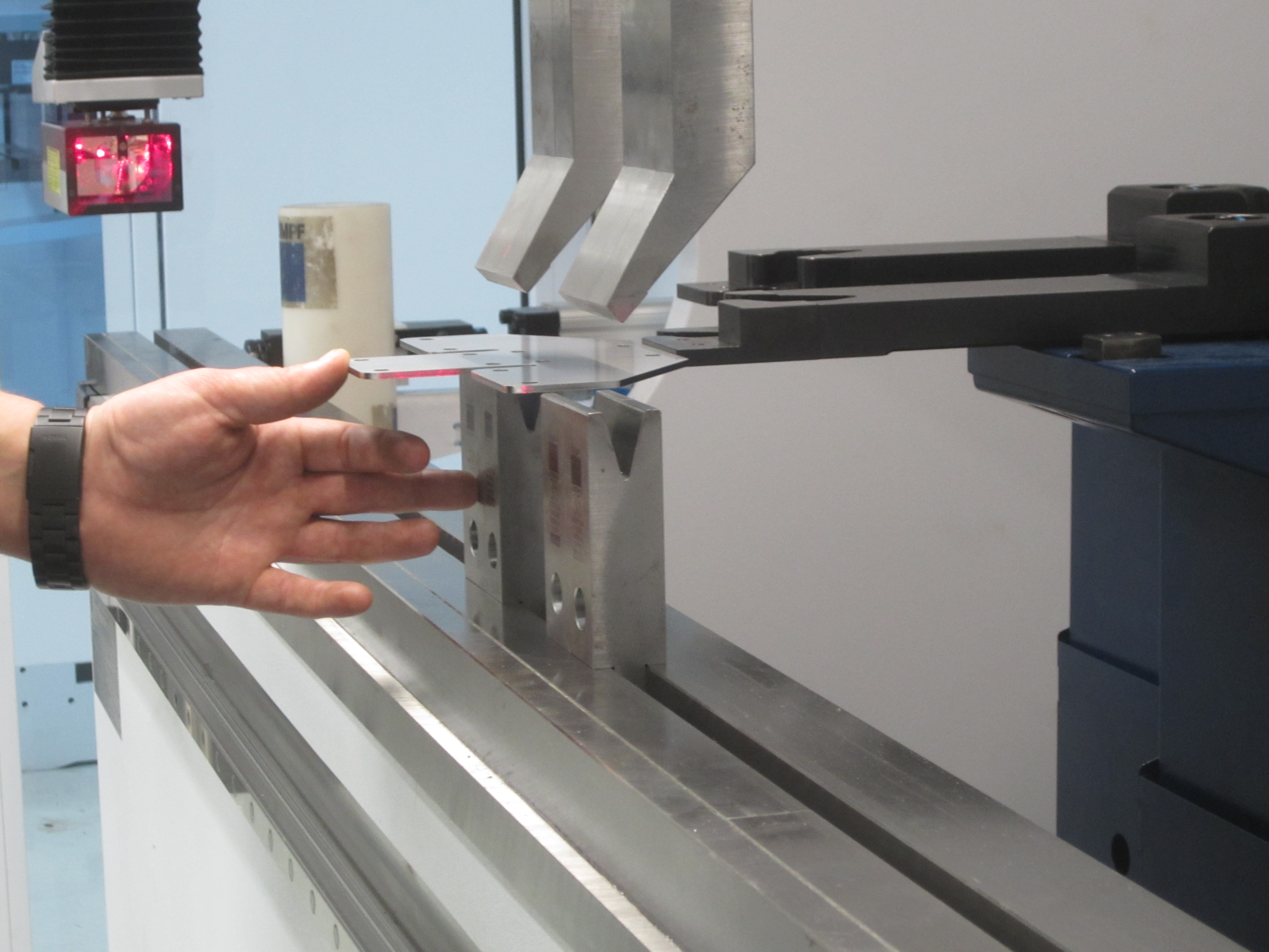
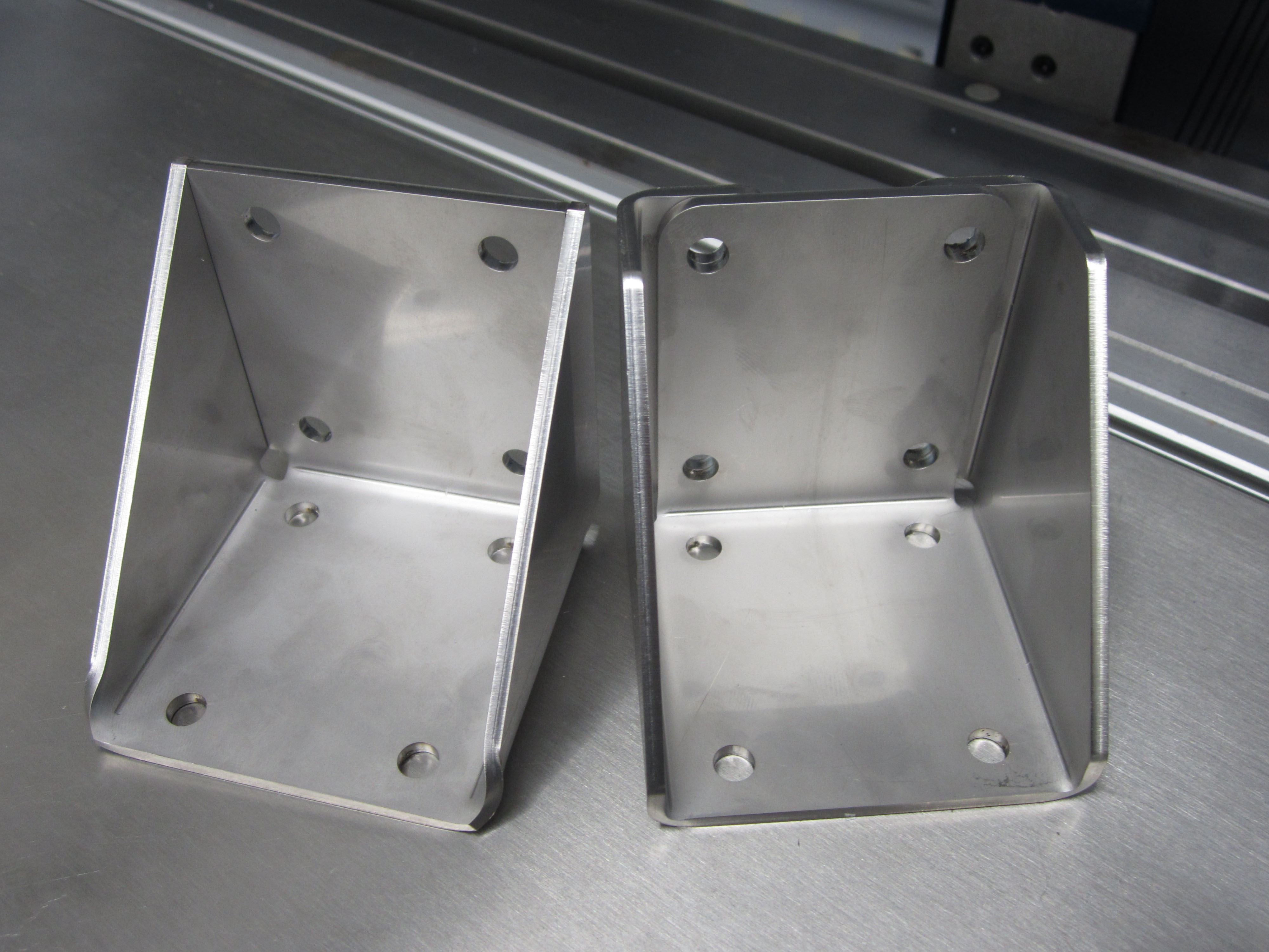
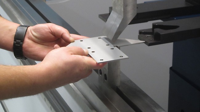
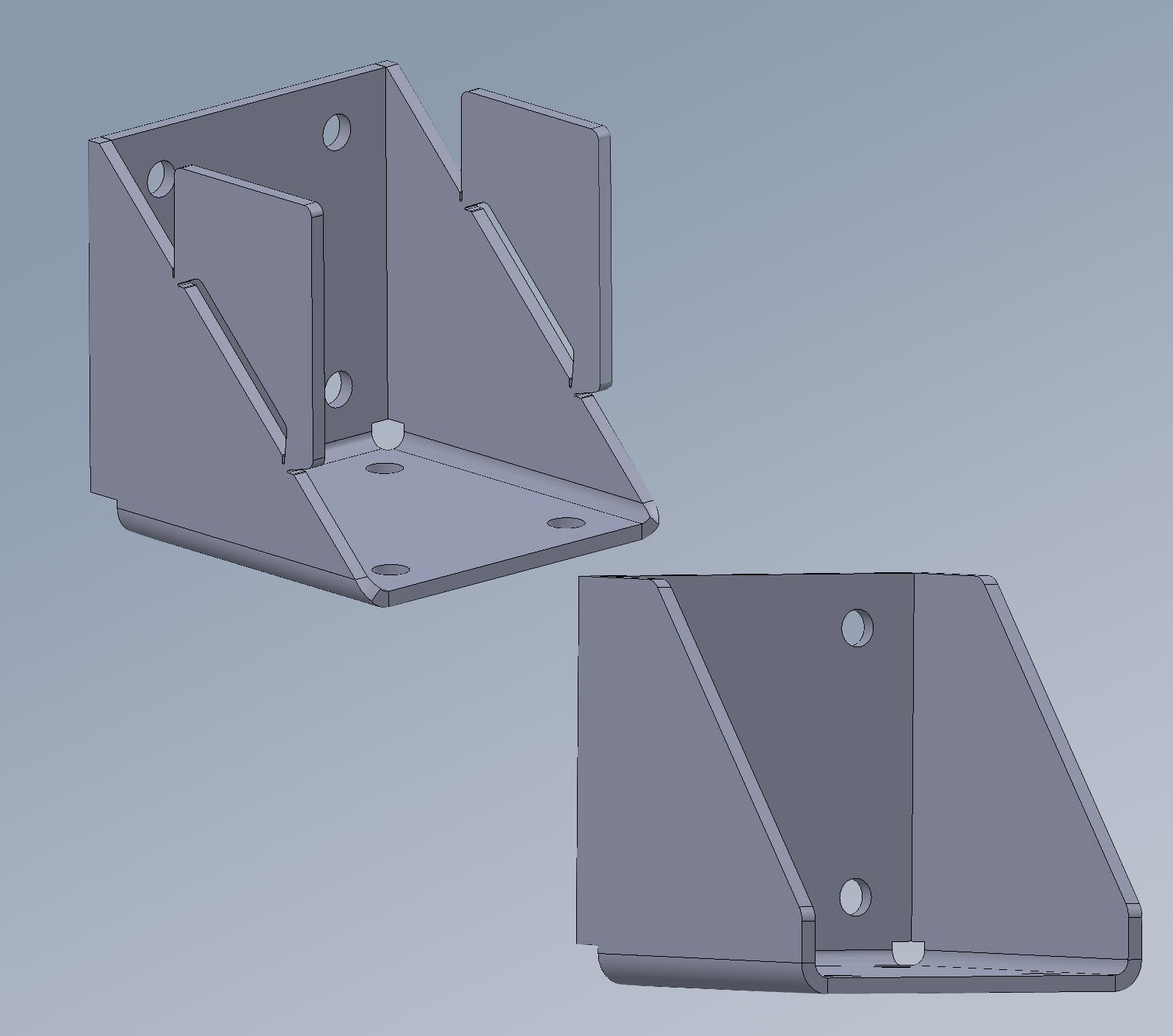
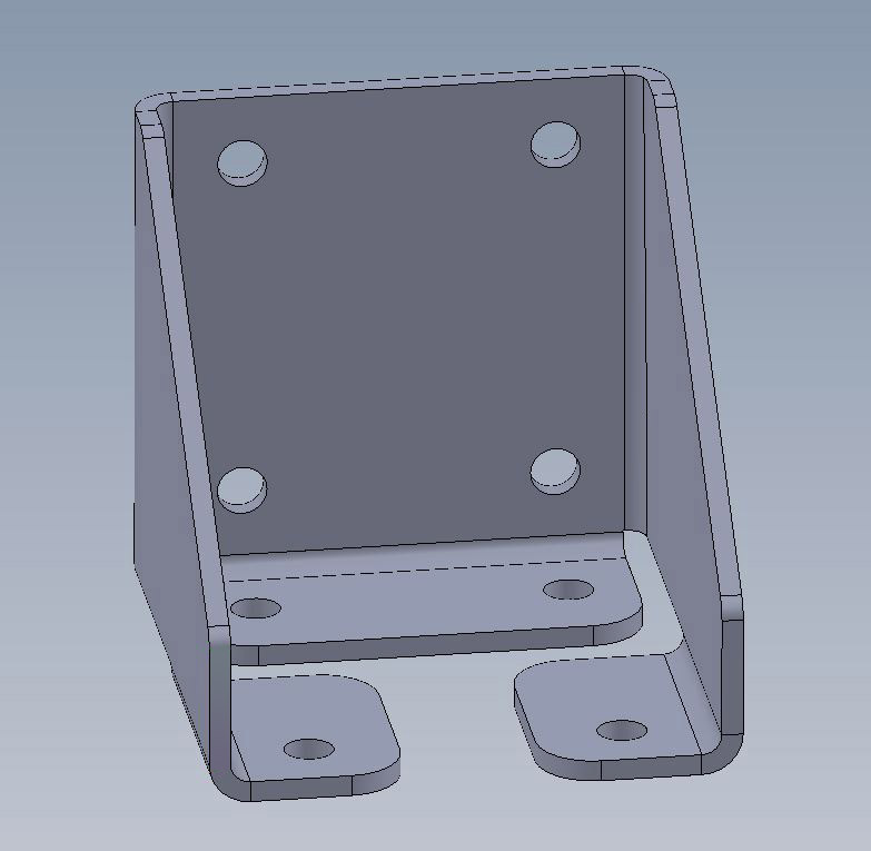
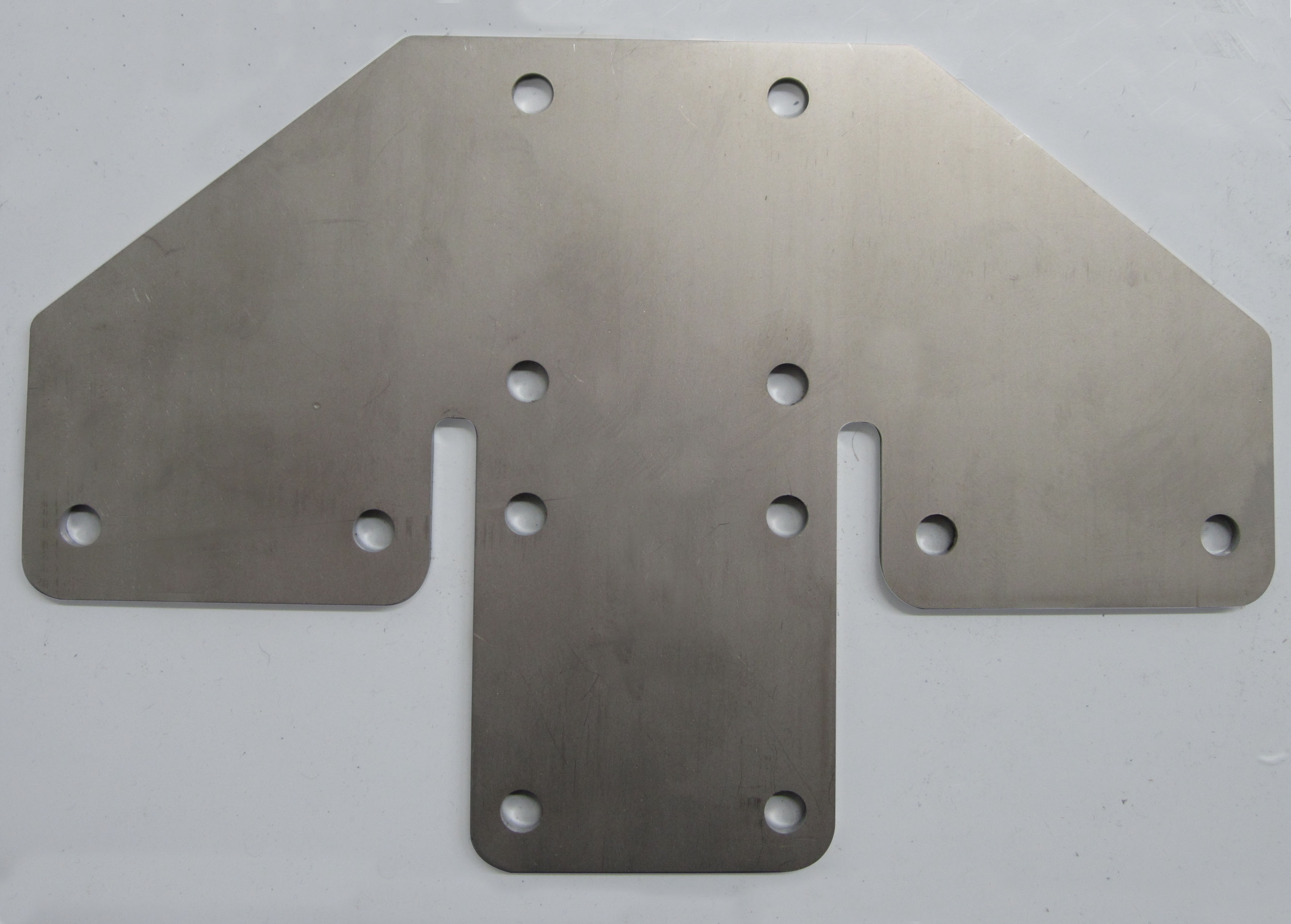
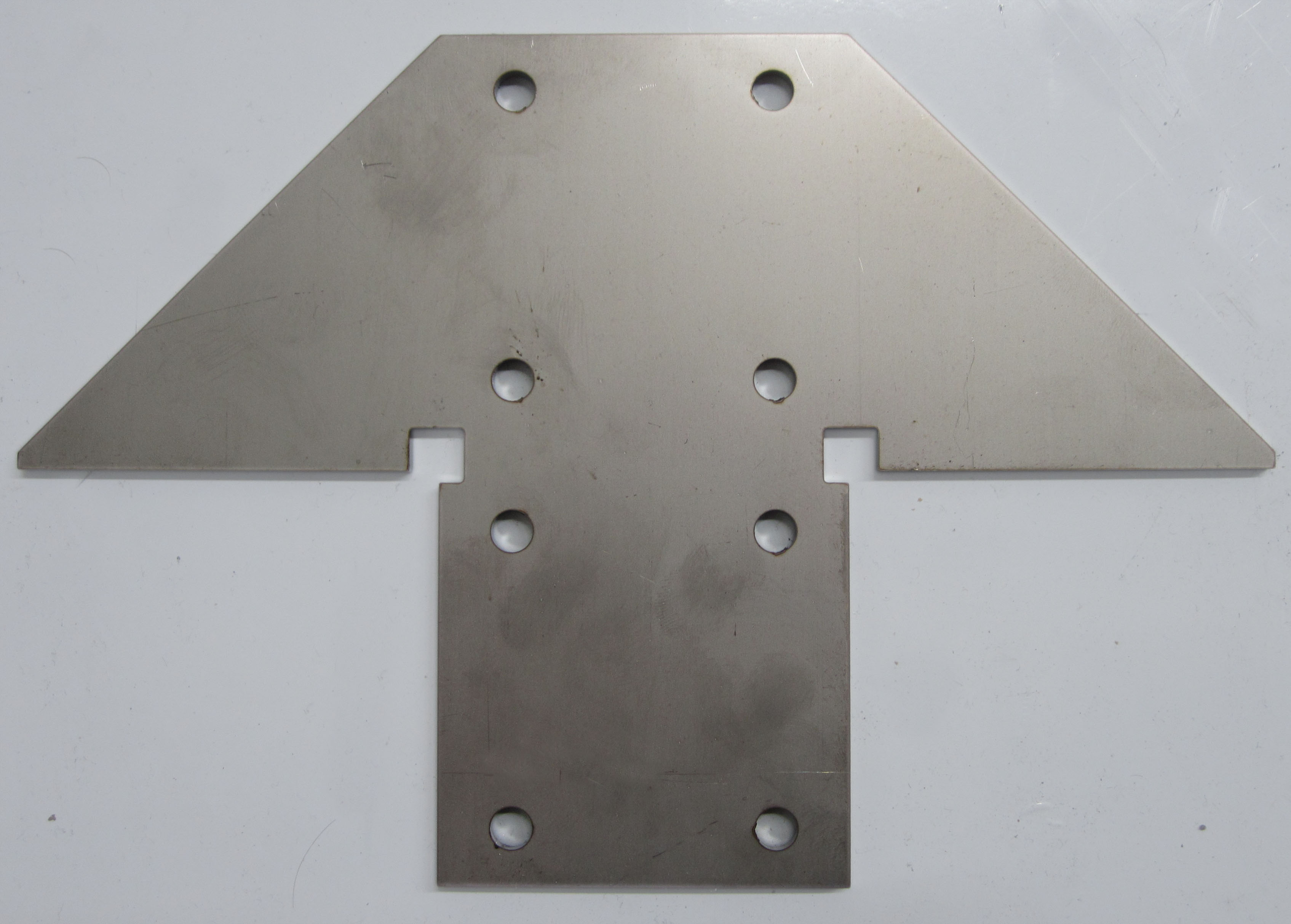
Figure 5. Increasing the size of the front flange leg so that it overlaps the gusset legs matches the strength of the original bracket. The part is formed with five bends using four hits from the press brake.
Figure 1. Even though this simple design is effective, frequently used, rendered in 3D files and appears to look perfect, several areas of its design and manufacturing process can still be improved. (second view)
Figure 2. Trying to bend the two side gussets perfectly into place is difficult because the small, sharp point must be kept perfectly set against a back gauge to form an exact part.
Figure 3. A few changes make this bracket stronger, easier to bend and more attractive.
Figure 4. Adding a front flange leg to adjust the lower mounting pad will bridge the sides of the bracket and help strengthen the part. (second view)


Whether starting out with a new part or reconsidering a well-established design, critiquing the design elements of a part can often lead to significant improvements in the manufacturing process. Even simple adjustments can frequently make a major impact, with redesigns leading to parts that (a) are faster to produce and more easily manufactured, (b) reduce or eliminate the need for additional processes such as welding, and (c) are more aesthetically pleasing. To visualize these advantages it is easiest to consider one of the most common design elements in machine design: the angle bracket. Used for support in countless applications, the angle bracket can be found almost anywhere, from simple joining to complex machinery. The variations to the physical size and shape of this element are equally wide spread.
Unlike castings where we can taper thickness and add fillets, the manufacture of angle brackets in sheet metal is limited to the thickness of the chosen sheet metal. If we decide to create this sheet metal angle bracket using a press brake, our scope is further narrowed. Most new designers would imagine a part which closely resembles the design pictured (Figure 1). This design is simple, effective, frequently used and rendered with a modern 3D CAD system. The part may look perfect, however, when it is actually produced we begin to see several areas of the design and manufacturing process that can be improved.
First, we see a flare out on the bent edge of the gusset. Second, it will be difficult to bend the two side gussets perfectly into place since the operator must keep the small, sharp point perfectly set against a back gauge to form an exact part (Figure 2). Lastly, the square bend relief adds a stress riser to the part and is unattractive. Very small improvements can be made to make manufacturing this bracket easier. Adding break-off flanges will greatly improve the operator’s ability to keep the part squared against the back gauge. But those flanges must eventually be removed, which adds time and scrap. Instead, we can make a small design adjustment to change the point of the gusset into a straight edge. We can also add a small flat edge where the gusset will be bent to eliminate the flare out. Finally, by adding radii or a slight contour to the part, we reduce stress risers while increasing the overall attractiveness. With these few changes, this bracket is stronger, easier to bend and is more attractive (Figure 3).
Next, we can look at lowering costs. Currently this design is cut on a laser. After it is cut, three bends are performed on a press brake before the part receives two welds on the inside of the bracket. The laser cutting and press brake operations are essential, but welding may not be necessary. In fact, if we can eliminate welding so only two manufacturing processes are required, we can significantly reduce the cost of producing the part. We can change our design so the welded seams are replaced with bends and the bottom bend is removed. For this we must split the base of the part, but since the mounting holes are far enough away from the bends, they can remain in their original position.
At first glance, it appears we have increased the number of bends by changing the mounting pad. However, with more careful consideration we recognize the press brake only requires three hits to create four bends. The bottom two bends can be formed with a single hit and the cost of bending will remain consistent with the original design. Unfortunately, by removing the bottom bend and splitting the mounting pad we have decreased the strength of the part. To regain strength, we must reconsider the design of the lower mounting surface. We can adjust the lower mounting pad by adding a front flange leg which will bridge the sides of the bracket and help to strengthen the part (Figure 4). To increase the stiffness of the mounting face, a fifth bend is added.
As with the last example, we can achieve all five bends with three hits from the press brake because the three “legs” are formed together in the first hit. When the three legs are fastened to a flat surface, the legs pull together and draw additional strength from the surface to which the bracket is mounted. This bracket will be stronger than the last design, yet it is still not as strong as the original. In our final design we look to regain the strength of the original bracket by increasing the size of the front flange leg to overlap the gusset legs we created when we eliminated the welds. The part still requires five bends formed with three hits from the press brake (Figure 5). The bracket has additional strength when bolted together which mirrors the strength of the original part without the additional costs associated with the welding process.
Here, we considered five different ways to change this bracket, but there are more possible options. Students attending our sheet metal design class are always interested in how many ways we can redesign a very simple element to increase manufacturability, reduce costs, and still perform the same job. This common bracket eliminated the need for welding and became easier to produce, demonstrating how small improvements in part design can lead to major benefits in time and money.
Subscribe to learn the latest in manufacturing.
Subscribe to learn the latest in manufacturing.
Industry News