Design for Laser Joining
Here are a few basic principles to consider when redesigning components and assemblies for the new capabilities afforded by laser welding.
Posted: September 20, 2013
A fabricator must strive for the most cost-effective manufacturing process while adhering to application demands, such as strength and weight requirements. As designers and product engineers have gained a deeper understanding of the properties, advantages and applicability of the laser welding process, it has become a prevalent and profitable manufacturing solution.
Compared to traditional joining techniques, laser welding provides the tools necessary for manufacturers to increase profits by making the most of this enabling technology. Here are a few basic principles to consider when redesigning components and assemblies for the new capabilities afforded by laser welding.
CONSIDERATION 1: FLANGES
When the flange is reduced or eliminated, there is a decrease in component weight and overall costs. In resistance spot welding, a typical flange may be upwards of ¾ of an inch (20 mm). This flange may be reduced to less than 3/8 of an inch (10 mm) since laser welding enables single sided, narrow beam access.
In fact, if an overlap weld is replaced by a simple seam design with a butt weld, this flange may be completely eliminated. Here, the material cost and weight savings can be substantial, depending upon the amount of resistance spot welding a particular application had prior to the redesign.
Scanner laser welding an automotive component. With high beam quality, scanner welding (or remote welding) is possible. This increases production speed and makes fixturing of parts easier. The beam is delivered to the robot via fiber optic. Laser welding is a fast, flexible and proven method for joining materials.
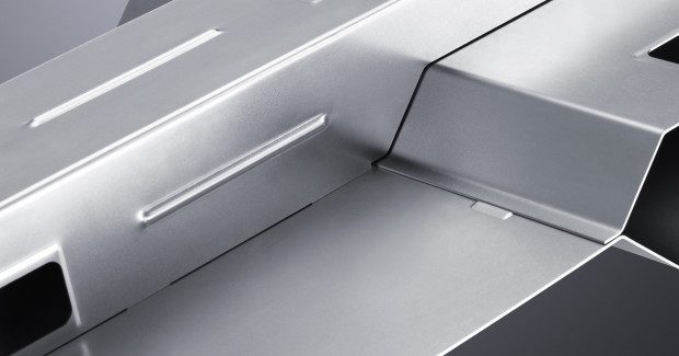
CONSIDERATION 2: SEAMS AND WELD SHAPES
A second consideration is to strengthen the weld to take advantage of continuous seams and different weld shapes that are possible with a laser. This has the potential to reduce the gage thickness, component weight, and cost of production. It is especially useful in the high-stress areas where spot welding is traditionally used.
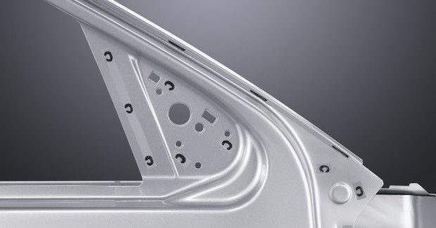
For example, laser stitches easily replace the resistance spot welding seam used to join the upper roof frame and lower rocker panel of an automotive body side but the real benefit is seen in critical areas for passenger safety, such as the A or B pillars. Here, continuous seams can replace stitches and eliminate the need for additional reinforcements. This feat is impossible with resistance spot welding.
Additional options enabled by the flexibility of the laser include long seams, “C” or “S” shaped welds, and parallel welds. By learning the strengths of a variety of weld joint styles, a design engineer can incorporate new strategies to meet the load and stress requirements of the application in a more cost-effective way.
In conventional resistance spot welding, access holes are required by the lower electrode. Thanks again to single-sided accessibility and the narrow beam, holes are no longer necessary when using laser welding techniques. By eliminating the holes, the strength of the structure will naturally increase, allowing fabricators to use thinner walled tubes or smaller sectioned tubes. Both methods will provide a reduction in weight while strengthening the joint and lowering costs.
CONSIDERATION 3: DESIGN FEATURES
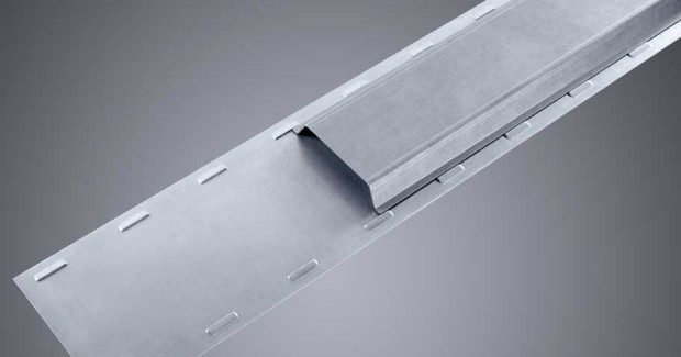
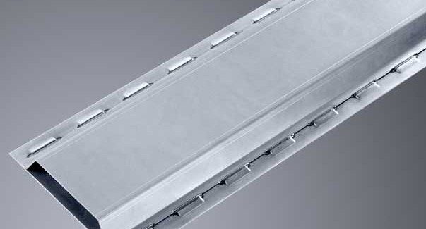
A final element to consider when designing parts for laser welding is incorporating special design features into the process. One example is the versatile and self-positioning K-joint (patented by our company). This can be used anywhere resistance spot welding is used to join sheet metal flanges or lap joints.
To prepare the parts for welding, small depressions are stamped at intervals along a joint contour. These indents serve as part locators and also the location of the weld seam. Since the K-joint can be welded from both sides, there is great flexibility when processing the part. As an additional benefit, zinc coated steels can be welded without issue because the K-joint transforms what would have been an overlap weld to a butt weld.
A second design feature, easily integrated into tube-to-tube, tube-to-flange, and bent tube designs, is a positioning tab or aid. These aids are simple yet flexible features used to improve clamping and assembly. In addition, they minimize potential assembly errors when a coding system is integrated into the location of each tab and slot.
Taking this a step further, a designer can use an interlocking connection to clamp two parts together. Bayonet or tab-and-slot style interlocking connections improve fit-up and create relative part locations to further simplify assembly. Expanding on the basic positioning aids, they also greatly reduce clamping requirements.
In sheet metal, slotted tabs can even be orientated at 180 deg so that slight flexing is required to make the connection between a part and its mating component with receiving slots. When flexing isn’t an option, the tabs can be bent after assembly to secure the connection.
The greatest rewards in cost and productivity are achieved when components are intentionally designed or redesigned to take full advantage of the laser joining process, yet early involvement of production personnel and a commitment to training, service and maintenance are also key to success. With these considerations, laser welding becomes much more than just a profitable and effective manufacturing solution.
Subscribe to learn the latest in manufacturing.

Industry News