An Application Guide for Scissor Lifts
To select an appropriate scissor lift for a specific application, here is the basic information that must be considered, including capacity, the nature of the load, the means of loading and unloading, the travel and lowered height, the platform size, speed requirements, power and duty cycle requirements, and more.
Posted: October 30, 2013


In the example given above, a lift model could be chosen that has a minimum platform size (and leg structure) of 48 in x 48 in. If this model were equipped with a 48 in x 54 in platform, the side edge loading would not have to be reduced at all because the minimum width on that model is the same as the chosen platform, so the derating calculation would be (48 in – 48 in) x 2 percent = 0 percent. The end load rating would still have to be reduced by 12 percent, but not having to reduce the side edge load rating by using the wider leg set can be a real advantage in some applications.
Usually extra wide models are 12 in wider and very wide models are 24 in wider than standard minimum width platforms. The maximum platform widths on these units are also proportionately wider. Check the exact models to be sure of the sizes.
ROLLING AXLE LOADS
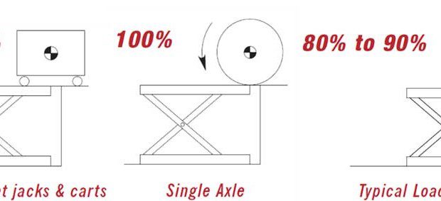
Axle loads may be expressed in static edge load terms by simply adding 50 percent for impact and dynamic forces. For example, a two-axle cart loaded to a 2,000 lb total weight would have a 1,000 lb axle load. To calculate the static load equivalent, simply add 50 percent for a 1,500 lb static load. If a 2,000 lb coil of steel or paper rolled over an edge, that is a 2,000 lb axle load that would be equivalent to a 3,000 lb static load. If the static load rating of the lift/platform configuration that is chosen does not meet the calculated requirement, a stronger or larger lift must be chosen that does.
There are two cautions in these simple axle load conversions. First, fully loaded fork trucks can have 80 percent to 90 percent of their total weight on their front axle, not the 50 percent that is used on other two-axle vehicles, therefore appropriate allowances must be made (see Figure 2). Secondly, very short carts rolling onto platforms with long overhangs can present situations where the entire cart is on the overhang.
This video is a guide for designing work access platform lifts that includes photographs and illustrates optional features as well as views of completed units to help explain the full scope of customization that is available. Our goal is to stir your imagination so that working together we can optimize a design to fit your application perfectly.
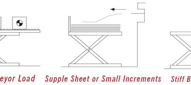
SLIDING LOADS
The loading that requires the most judgment is the sliding load (see Figure 3). When a load is sliding onto a conveyor, there is less of an impact factor on the lift than a rolling axle would apply and the end conveyor roller (and platform edge) would never see the entire weight of the load because of deflection within the lift mechanism. In the case of supple incremental loads such as sliding sheets of paper onto a unit, the edge loading and impact are trivial and not a factor in selecting a lift.
In the case of an ingot of lead being slid onto a platform, impact and edge loading requirements may be the deciding factor in lift selection. Therefore when considering the entire range of applications, judgments must be made about all of the following factors:
(1) Friction and impact: Conveyor virtually eliminates friction for items being loaded onto a lift. Steel items sliding on steel platforms usually have a coefficient of friction of approximately 30 percent. Rubber-based items can have extremely high coefficients of friction. Since sliding forces are more horizontal than vertical, they usually can be ignored except for extreme situations. Impact becomes a factor when loads are traveling at high speeds. If either of these factors is of concern, please allow the engineers to make the value judgments.
(2) Horizontal impact against stops: Many conveyor applications require stops be added to the lifts, either by the lift manufacturer or by the lift user. The horizontal force imparted by the stop must be parallel to the leg members and shock absorbers should be considered. Horizontal impact forces must not impact the unit perpendicular to the leg members or there will be structural damage. When consulting with the factory, be sure to have the weight of the moving object and the speed of movement.
(3) Incremental layers: Each load increment must be considered as a percentage of both the total lifting capacity and the edge load rating. Small percentages are no factor and large percentages may dictate choosing units with higher edge load ratings. If the incremental layer being moved onto a raised lift is large, then consideration of items 4 through 6 below becomes more important.
(4) Footprint of the load increments relative to the overall platform size: If the footprint of the increments matches the platform size, then the load will probably come onto the unit in a gradual manner and edge loading will be fairly negligible. If the footprint is relatively small, estimates of the edge loading that will be produced become important, as do items 5 and 6 below.
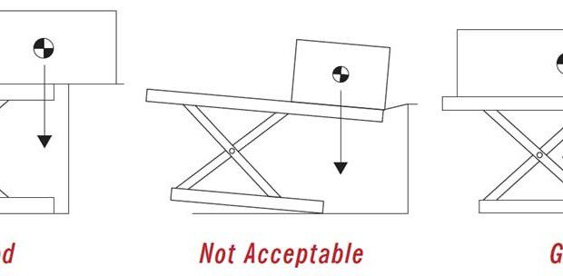
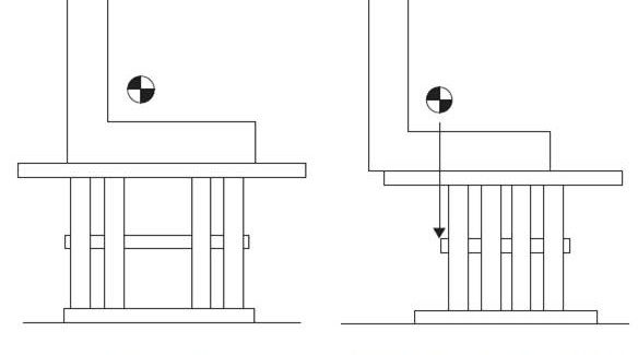
(5) Footprint of the load increments relative to the minimum platform size (supporting leg outline): If the proposed lift will be equipped with a minimum platform size, then the load will always transition onto satisfactory leg support. If there is a large oversized top, it is necessary that the load have more than 50 percent of its footprint and weight over the supporting leg outline when it is no longer supported by the adjacent surface.
(6) Location of center of gravity of the load increments relative to the minimum platform size (supporting leg outline): When items are not uniform in shape or weight, be careful that the center of gravity of the load is always within the supporting leg outline, (minimum size platform outline) when the load is no longer supported by the adjacent surface (see Figures 4a, 4b).
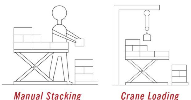
PLACED OR STACKED LOADS
Some loading produces no edge loading requirements. Manually stacking layers of boxes is a good example. This type of operation imposes negligible impact and no edge loading. Vertical loading with a crane or other overhead device is a good example of no edge loading, but the possibility of very high impact to the lift (see Figure 5).
With a maximum capacity load, a lowering speed of 17 fpm will produce acceptable impact loads on opened lifts. Speeds in excess of 17 fpm may create damage to cylinder packings, hoses or structural members. Most industrial cranes are limited to speeds of 17 fpm or less, but applications with vacuum assist lifts, vertical conveyors or free fall applications, may produce destructive impacts. Obviously, the slower the rate of vertical impact, the better.
TRAVEL AND LOWERED HEIGHT
Travel refers to the vertical movement of the unit. It should not be confused with raised height, which is the sum of the lowered height and travel. The only time the travel is the same as the height above ground is when a unit is recessed into a pit. The vertical travel of a unit can never be increased, but it can be decreased or limited with limit switches or mechanical stops. Units with excess travel are chosen for some applications, so that longer platforms can be made available.
Published lowered heights can never be reduced, but they can be increased by either blocking units open or building up beneath the base frames.
Subscribe to learn the latest in manufacturing.

Industry News