An Application Guide for Scissor Lifts
To select an appropriate scissor lift for a specific application, here is the basic information that must be considered, including capacity, the nature of the load, the means of loading and unloading, the travel and lowered height, the platform size, speed requirements, power and duty cycle requirements, and more.
Posted: October 30, 2013
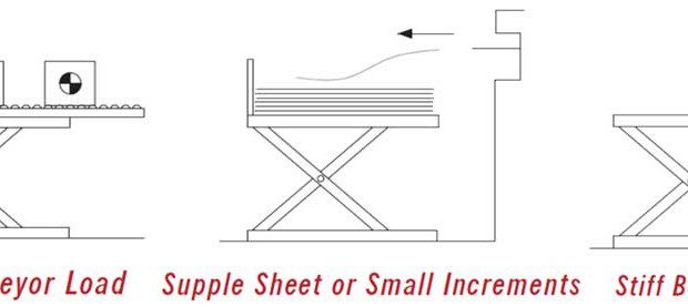

PLATFORM SIZE
The platform sizes must fall within the maximum and minimum sizes shown in the lift catalog. Note that if something is affixed to a platform like a conveyor or other device, it must also fall within the maximum size constraints listed for the platform, as the attached device in fact becomes the platform.
SPEED REQUIREMENTS
Usually the standard speed offered with each lift model is satisfactory for most applications, but occasionally faster speeds are required. The formula for horsepower is work (force x distance) divided by (550 x time). Therefore, the shorter the amount of time to do the work, the more horsepower that will be required.
In the case of units with internal power units, any increment in horsepower size will require moving the power unit externally because the larger motors will no longer fit within the structure. As horsepower goes up in size and costs, so do the electrical controls, hydraulic pumps and valves. Costs often rise quickly.
To combat these steep price increases, some lift users have suggested that their applications only require that the lift only go up fast “empty” and come down slowly with a load. It should be understood that from a safety aspect, a lift should never be produced nor used that cannot lift its maximum loaded capacity, in case someone gets a body part caught within the lift. Speed cautions begin at speeds of 15 fpm to 24 fpm. At these speeds enough energy is built up so that damage can occur to the units over time unless something is done to decelerate the units at the limits of travel.
The worst conditions are going up empty and down fully loaded. In this speed range, depending on the actual application, simple things can be done like adding shock absorbers at the bottom of travel, providing adjustable flow controls or simply adding limit switches at the limits of travel. Good descriptions of travel increments and load increments will provide the necessary information to determine what, if any, precautions should be taken.
Speeds greater than 24 fpm will definitely require a more sophisticated deceleration system. Speeds of 100 fpm can be provided, but position sensing and special hydraulics are mandatory to preserve lift life. Very high speeds can triple or quintuple the cost of a lift.
POWER AND DUTY CYCLE REQUIREMENTS
The actual power available at the intended location of the equipment should be confirmed at the beginning of the selection process. Some units will not operate at catalog speeds on single phase currents. On air applications, PSI and CFM availability at the equipment site must also be confirmed.
When considering the duty requirements of the lift, it is necessary to think in terms of two systems, the lift mechanism and the power unit. It is necessary to know whether the lift application requires full stroke movement “up” or “down”, or whether there will be a series of incremental “jogs” in one of the directions. Specifically needed are the time intervals between operations and the direction and size of movement in each operational increment. Finally, the total number of cycles per hour, day and year should be calculated.
Applications with many short jogs in quick intervals may require the need of a special power unit. If the jogs are in a downward direction, the standard lowering solenoids are of a continuous duty type and nothing needs to be done. However, if the increments are in the “up” direction, the standard motor would not take the frequent motor starts without overheating. Therefore, the options to consider are going to an air operated unit, air over water unit, or a continuous running power unit. (See the power unit options for the specific table model that is being considered.)
Applications without frequent jogging are usually easier on the power units, but check the operational sequence against the rule of thumb of eleven seconds off for every one second on with full loads. Keep in mind that most applications seldom see full loads. If overheating is an issue, consider a continuous running power unit or check with the factory for other power unit options.
Once the total number of cycles per year are calculated, that number can be compared to the “warranty life” and “expected life” as explained by the lift manufacturer. Note that there is a large difference in the warranty life of a standard unit and an ultra-high cycle unit, just as there is a large difference in price. If the application being considered falls somewhere in-between, contact the manufacturer to see if a modified standard unit can be designed to better fit the application and the budget.
SPECIAL FEATURES & ACCESSORIES
These items are generally divided into two categories, standard options which are included in the catalog and price lists and those unusual items that must be priced by the factory.
Items that require factory consultation include:
- Special environments such as freezers, proximity to high heat, or damp locations
- Hazardous environments such as explosion proof for dust or for vapor (Note: The lift manufacturer should supply explosion proof components, but the installing electrician is the only one who can guarantee compliance to local electrical codes for explosion proof.)
- Special finishes such as stainless steel, polyurethane paints, epoxy paints
- High cycle requirements that fall between standard units and ultra-high cycle units
- Any requirements that do not fit within any of our standard groups of equipment
- AC or DC self-propelled units
- Bellows and roller shades
Items shown in the lift catalog and price lists: (see accessory sections):
- Power units that are deluxe, continuous duty or continuous running
- Push buttons, footswitches, and other control options
- Oversize platforms and platforms with bevel toe guards
- Portability options such as wheel and dolly sets and casters
Advanced Lifts, Inc., 701 Kirk Road, Saint Charles, IL 60174-3428, 630-584-9881, Fax: 630-584-9405, www.advancelifts.com.
Subscribe to learn the latest in manufacturing.

Industry News