Back to Basics: How Air Gaging Works
Air gaging technology has its roots back over 70 years and is today a viable and highly reliable method for many applications in industries where a high volume of parts is produced or where the precision of hard-to-access dimensions makes other measuring techniques impossible.
Posted: April 6, 2014
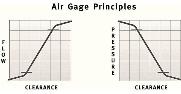


Air gaging relies on a law of physics that states flow and pressure are directly proportionate to clearance and react inversely to each other. As clearance increases, air flow also increases and air pressure decreases proportionately. As clearance decreases, air flow also decreases and air pressure increases.
This is accomplished by having a regulated air flow that travels through some type of restriction such as a needle valve or jeweled orifice and then through the nozzle in the air tool. As the obstruction (workpiece) is brought closer to the nozzle, air flow is reduced and the back-pressure is increased. When the nozzle is completely obstructed, the flow is zero and the back pressure is equal to the regulated air. Conversely, when the nozzle is open to the atmosphere, air flow is at a maximum and the back pressure is at a minimum.
BRIEF HISTORY OF AIR GAGING
Air gages were first developed in France before World War II by a carburetor company that was looking for a more reliable method of measuring its carburetor jets. These air gages used a simple back pressure technology and provided the basis for the development of virtually all air gaging styles used today. This design was much improved in 1943, when a U.S. patent was granted for a simple back pressure system that incorporated the newly developed air pressure regulator. Many improvements in air gaging systems and styles have been developed through the years.
TYPES OF AIR GAGING
There are several varieties of air gaging systems that include back pressure bleed, differential and flow type systems.
The back pressure bleed system is the most versatile. Tooling from different air gaging systems may be used with this type. It is configured with an air pressure regulator to control the incoming air pressure to ensure maximum linearity. It is the second restriction that allows the user to adjust for different air gage tooling by adjusting the incoming air pressure to match the style of air tooling used. This type uses two setting masters to calibrate. The masters are typically at the MIN and MAX of the tolerance of the workpiece. This allows for linearity of the measurement through the entire measuring range. Because it is a two master system, each time you calibrate, you are compensating for any wear, dirt build-up or minor damage to the tooling.
The differential system divides the air stream into two fixed restrictions. One side ends in a zero valve, which balances pressure to the fixed second leg of the system, which ends at the air ring or plug. The difference between these two legs is measured by a differential pressure meter that bridges the two legs. This type uses a single master to set it to zero. Tooling for this type of system needs to be ordered for each particular magnification. This system is not as forgiving with worn or damaged tooling because you are using a single calibration point. Any part not made near the zero is more likely to have an inaccurate reading. This becomes more of an issue as you reach the outer limits of the tolerances.
The flow system is measured and read in a flowmeter tube that supports a float. This system uses two masters for calibration. It is similar to the back pressure bleed system in its accuracy across the tolerance range. The range of magnification is adjusted by changing flow tubes and scales and is not as simple as the back pressure bleed system. The flow system requires a much higher volume of air which requires much larger nozzles. Because the nozzles are larger, the nozzle must be kept closer to the part and therefore has a smaller nozzle drop. This can shorten tool life. The flow system can be used with long hoses without affecting the response time of the amplifier which makes it the ideal candidate for long holes such as gun barrels.
WHY USE AIR GAGING TODAY?
Air gaging is a very fast, efficient and reliable method of measuring. It is designed to be used on workpieces with tolerances of 0.005 in or smaller. The resolution and repeatability of the measurement can be in the millionths of an inch. Because air gaging is a non-contact method, it is useful for measuring soft, highly polished, thin walled and other materials susceptible to marking. Air gaging is extremely easy to use and requires no special skills for the operator. Multiple operators will achieve the same or nearly the same measuring results when measuring the same part, thus taking operator technique out of the measurement results. This is a problem when you using a contact gage such as a micrometer or dial bore gage.
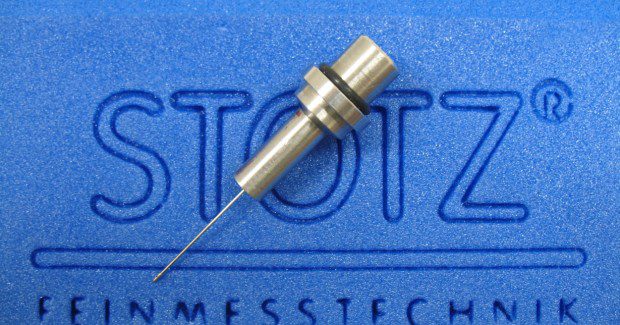
Air gaging can be used to measure complex geometric tolerances such as diameter, taper, parallelism, squareness, flatness and matching of components in a very fast and efficient method. These may not be able to be checked with fixed limit gaging or may be costly and time consuming to check in a different way. The size of probes continues to get smaller and smaller and can now be as small as 0.6mm (0.024 in) in diameter.
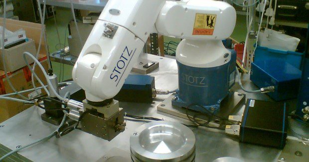
Many of today’s columns and/or measuring computers can become an integral part of the manufacturing cell with communication to robotic loaders and the ability to send offset values to the machine, which allows for around the clock manufacturing with 100 percent inspection of workpieces.
Air gaging systems operate at air pressures that can remove contaminates such as abrasive particles and coolant, which will eliminate the need for a separate cleaning in most applications. The air tooling has no moving parts and therefore has a very long and dependable service life.
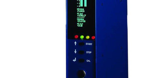
Air gaging technology is continually improving as computer technology continues to evolve. These systems can range from simple desktop readouts to full SPC computers with contour scanning capabilities. As manufacturing requirements continue to become more complex, air gaging technology evolves to meet the demand. For these reasons, air gaging will remain a viable measuring solution for generations to come.
TOP TEN REASONS TO USE AIR GAGING
Air gaging technology has its roots back over 70 years and is today a viable and highly reliable method for many applications in industries where a high volume of parts is produced or where the precision of hard-to-access dimensions makes other measuring techniques impossible. This includes the fast-growing laser technology, in some cases.
Air gaging is based on the simple principles of physics that flow and pressure are directly proportional to clearance and that they react inversely to each other. In layman’s terms, this means there is a fixed relationship between the object and the airflow, one that can be tracked quite precisely. The flexibility of air gaging means it can be used to measure flatness, roundness, squareness, taper, straightness and matching between pairs of joined surfaces, on connector bodies, for example.
Here are ten quick ways that demonstrate the advantages of air gaging in a job shop. Unlike that TV talk show host, these are not put into any order, as the value of air gaging is also directly proportional to your shop’s needs and budget considerations. Here we go:
- Fast. The measurement is extremely fast. Great for 100 percent inspection of high-volume parts. Measurement takes only seconds and can be done inline, in many operations.
- High precision measuring results. Air gaging can repeat measurements in the sub-micron range (millionths of an inch range) with a very high degree of accuracy.
- No special training. Multiple operators will achieve similar results in measurements without special training. Ideal for the busy shop where everybody multi-tasks nowadays.
- Easy to use. Goes hand in hand with no special training, as air gaging requires just a few quick steps. On more advanced systems, all quality data are integrated and downloadable via various ports and protocols.
- Non-contact. Air gaging is non-contact and will not damage your parts. Sensitive components and delicate webbed structures can be measured without risk of damage.
- Self-cleaning. Because the air is blowing across the surface being measured, any dust or coolant will be cleaned from the part. This saves considerable prep time and related costs for the shop. Accuracy is in no way compromised.
- No moving parts. This provides for longevity of the gaging system. As long as the air supply is consistent and clean, air gages can last for many years.
- Small diameters. Air gaging can be used to measure extremely small diameters. Less than .6mm on an inside diameter is typical.
- Taper measurements. Air is a quick and accurate way to measure tapers. Can display in degrees, minutes, seconds.
- Small lands or thin walled parts. Will not distort the part on thin walls. Control of the airflow on today’s more sophisticated systems is highly adjustable and, again, does not affect the reliability or accuracy of the measurements.
Stotz has been a leader in gaging technology for almost 60 years, constantly striving to improve designs and develop new products to solidify their position as a leader in measuring technology. The Stotz customer base consists of manufacturers and suppliers in the automotive, aerospace and medical industries.
Advanced Machine & Engineering Co., is a manufacturer located in Rockford, IL, serving the Machine Tool Industry with precision components and accessories, including spindle interface components, workholding devices, and, through our sister company, Hennig, machine enclosures, chip removal and filtration systems. The Fluid Power – Safety markets are served with cylinder rod locks and safety catcher devises; and the Production Saw market with our AMSAW® carbide saw machines and Speedcut blade products. AME has manufacturing partners and customers around the world and across the U.S. www.ame.com
Hennig, Inc. design and produces custom machine protection and chip/coolant management products for state-of-the-art machine tools. Hennig products are designed to protect against corrosion, debris and common workplace contaminants. Manufacturing facilities are located in the U.S., Germany, Brazil, India, Japan, France and South Korea. Repair centers are located in Machesney Park, IL; Chandler, OK; Livonia, MI; Blue Ash, OH; Mexico City, Mexico and Saltillo, Mexico. www.hennigworldwide.com
Advanced Machine & Engineering Co., 2500 Latham Street, Rockford, IL 61103, 815-316-5277, Fax: 815-962-6483, kris@ame.com, www.ame.com.
Subscribe to learn the latest in manufacturing.

Industry News