


Prerequisites for High Surface Quality
The flawless surfaces required in mold making demand large cutting volumes during the roughing sequence, but a perfectly finished surface at the end. This analysis from Heidenhain examines how, along with high quality machine tool mechanics and control performance, the optimal milling result necessary to do this depends heavily on the measuring technology.
Posted: April 30, 2014


It takes much time and effort to manufacture perfect surfaces. The sculpture “Cloud Gate,” for example — a sculpture by the artist Anish Kapoor in Chicago’s Millennium Park — was polished by 24 specialists for several months as the final step. The stainless steel sculpture, with over 99 metric tons and the gigantic dimensions of 10 m x 20 m x 13 m, features a perfect, seamless surface that mirrors the Chicago skyline.
In the same way, flawless surfaces are likewise a frequent goal in the machine tool industry, and particularly in mold making. Here, however, economic aspects play an important role. Manufacturing parts with tight tolerances and high surface quality in a short time presents a special challenge. The manufacture of high-quality workpieces in mold making demands large cutting volumes during roughing on the one hand while requiring a perfect surface after finishing on the other.
Only if surface quality is optimal is it possible to avoid subsequent cost, e.g. through manual polishing. Besides the quality of the machine’s mechanics and the corresponding performance of the control, the third column responsible for an optimal milling result is the measuring technology.
To achieve high part surface quality, the encoders that provide signals with extraordinarily small deviations within one signal period (interpolation error) are of crucial importance. Interpolation errors are responsible, for example, for periodically recurring irregularities in form on the workpiece surface, which are particularly disturbing in mold making.
SURFACE DEFECTS STAND OUT
The human eye is very sensitive to structural changes or even the smallest defects on a surface. A pixel error on the monitor, for example, with a display comprising up to five million pixels, is immediately visible. The human eye is even more sensitive to periodic surface faults.Test workpieces show that periodic form errors of as small as 0.2 µm can be clearly visible. Particularly in mold making, these form deviations — although they have no influence on accuracy — are disturbing and require expensive rework.
POSSIBLE REASONS FOR PERIODIC SURFACE ERRORS
Surface errors are visible on part surfaces as shadows or fluctuations in contrast. From the usual vision distances, the human eye perceives them as disturbing. They can be attributed to fundamentally different causes:
- Vibrations of the machine that disturb the machining process
- Short-period errors of the axis encoder (position errors within one signal period, i.e. interpolation error)
This technical Information describes surface errors caused by position error within one signal period.
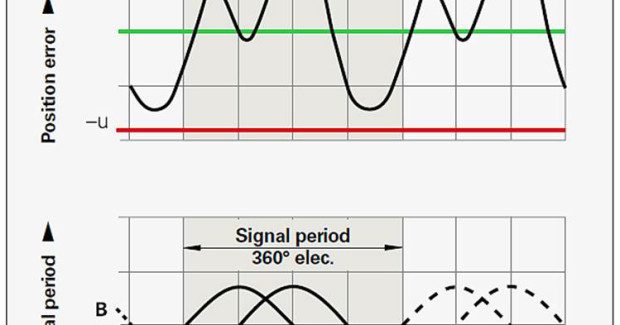
POSITION ERRORS WITHIN ONE SIGNAL PERIOD
The resolution provided directly by an encoder is usually insufficient for modern machine tools. Interpolation processes are therefore applied that subdivide the periodic analog — typically sinusoidal — scanning signals A and B. Interpolation factors of 4096 (12 bits) and more are quite usual. This makes it possible to start from measuring standards with relatively large graduation periods and attain the measuring steps of 0.1 µm and less that are needed for controlling machine tools. Encoders are available that achieve measuring steps of 0.001 µm.
The interpolation processes operate faultlessly as long as the two sinusoidal output signals are ideal, i.e. have the exactly the same shape, amplitude, on-off ratio, and are phase-shifted to each other by exactly 90 deg. Deviations generate errors that repeat themselves with each period of the scanning signals. One therefore speaks of errors within one signal period or interpolation error.
The size of position errors within one signal period are determined by the following:
- The size of the signal period
- The homogeneity and period definition of the graduation
- The quality of scanning filter structures
- The characteristics of the sensors
- The stability and dynamics of further processing of the analog signals
EFFECTS OF POSITION ERRORS WITHIN ONE SIGNAL PERIOD
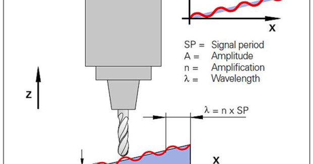
The mold making industry is demanding workpieces with increasingly complex geometries. In five-axis machining, all combinations of axis movements are common. If an inclined or curved machining surface is manufactured through the interpolation of multiple NC axes, the interpolation error can be seen directly on the workpiece.
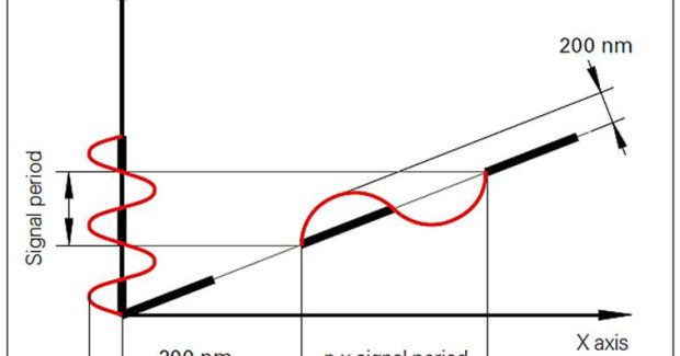
This becomes particularly apparent when an inclined surface with a small angle is machined. The interpolation error of the encoder in Z direction can become visible by projection on the inclined workpiece surface. Because of the inclination, an n-fold enlargement of the signal period appears in the tool path. While the axis in Z direction moves by only one signal period, the X-axis moves n times more. A wave appears on the inclined workpiece surface with a wavelength that corresponds to the n-fold signal period of the Z-axis encoder.
Because all sorts of inclined surfaces are manufactured during the machining of free-form surfaces, there will always be the corresponding amplification of the signal period. A wavelength of 0.5 mm to 5 mm is especially easy for the human eye to detect.
With an interpolation error amplitude of less than 100 nm, the workpiece surface has a flawless appearance. Starting from an interpolation error amplitude of approx. 200 nm, the effects on the milling results becomes visible. Greater interpolation error results in optically disturbing form deviations.
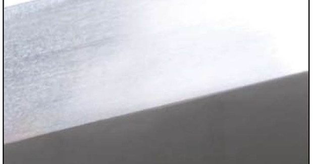
MACHINING EXAMPLE
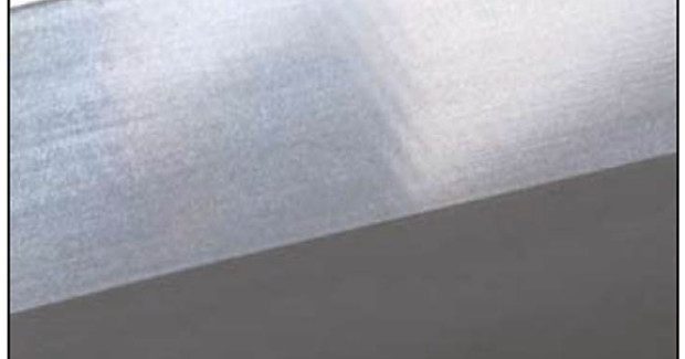
The example workpiece (see Figure 4) is manufactured in multipass milling with a ball-nose cutter, ⍉12 mm. Different sizes of interpolation error exist for each of the three machined surfaces. An encoder with very small interpolation error was used for the top workpiece in Figure 4. In this case, the typical interpolation error is significantly less than 100 nm. The workpiece surface appears perfect.
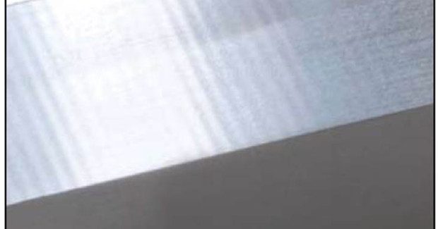
Encoders with larger interpolation error present a different picture: because the feed axes follow the high interpolation error, a conspicuous wave pattern appears on the workpiece surface. The middle picture in Figure 4 shows the result of milling if the encoder has an interpolation error of 200 nm. A wave shape is clearly visible. With 500 nm interpolation error, the workpiece surface has a very prominent wave shape (Figure 4, below).
CONCLUSION
Encoders with very small interpolation error are necessary in order to mill workpiece surfaces without a visible wave pattern. Certain linear encoders are distinguished by very high accuracy and durability.Their high signal quality is achieved through an extremely precise DIADUR measuring standard and the highly accurate single-field scanning method. This is the basis for encoders with very high precision and very small position error within one signal period.
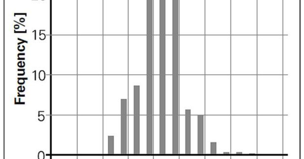
The maximum interpolation error of the LC family of linear encoders from Heidenhain Corporation (Schaumburg, IL), for example, lies significantly below 100 nm. Figure 5 shows the RMS values of interpolation errors in a series of measurements of 1,000 LC 183 model encoders. The RMS value of the interpolation error for 85 percent of the tested encoders was less than 12 nm. As the successor model, the LC 115 features lower RMS deviations.
Heindenhain Corporation, 333 E. State Parkway, Schaumburg, IL 60173-5337, 847-895-0945, kstoneski@heidenhain.com, www.heidenhain.com.
Subscribe to learn the latest in manufacturing.


Industry News