


A Practical Approach to Bending Length Precision
To hit those very small flange length tolerances on our prints, we need to master that material stretch. This means we need to understand not just the material, but also how the press brake tooling being used to perform the bend will change the amount of stretch and impact the size of the blank.
Posted: December 22, 2014

It’s no secret that a higher standard of precision is the trend in metal fabrication today. Throughout a fabrication process chain the need for increased precision is driving collective efforts and directing investments. Machine tools are built with more accuracy, higher grade materials are specified, the tolerances on manufacturing prints are smaller, and even the software in the front office is more detailed.
All of this brings fabricators closer to the goal of eliminating waste and non-value added time. In the middle of all of this, where flat sheet steel becomes a 3-dimensional object, lies the press brake operation. The peculiarities of metal forming and the manned nature of press brake machines means that this part of the process chain can present serious challenges to the goal of ultimate precision.
UNDERSTANDING MATERIAL STRETCH
The science describing how metal forms elastically during the bending process is generally understood, however the basics are worth repeating briefly. When a piece of sheet metal is formed between a punch and die, two very specific physical processes occur inside the bending metal. The grain structure along the inner surface of the bend is compressed, while the material structure of the outer surface is in tension. In practical terms, this means the material will stretch. The amount it stretches during bending determines how big the flat part must be to start with, so that once all the forming is done, the finished product is the right size. To hit those very small flange length tolerances on our prints, we need to master that material stretch.
http://youtu.be/2HUWB87S4Yc
The value of the material stretch is referred to by many names, including k-factor, bend deduction, bend allowance, setback, and shortening factor. Though they may be defined a little differently, all of these technical terms refer to the development of a flat blank for forming. As the radius of the bend changes, the amount of stretch also changes. So, not just the material but also the press brake tooling used to perform the bend will change the amount of stretch and impact the size of the blank.
DETERMINING THE STRETCH
To develop the correct flat pattern and make an accurate finished product, manufacturers have turned to several strategies. The very best technique for mastering flange length accuracy is the empirical method; that is, learning your bend factors on your equipment with your material and tooling. Here we will review a very simple and extremely effective procedure.
For this test, you will need a micrometer. Since the material stretch varies with different material types and thicknesses, and also different combinations of tools, start with your most commonly-used upper and lower tool sets and most commonly-processed materials. From here, you can expand your empirical dataset to include new material and tool combinations. Material samples should be square or rectangular. For thinner materials, a flat piece between 2 in x 2 in and 3 in x 6 in works well. For thicker materials, adjust the size of the sample based on the die opening used.
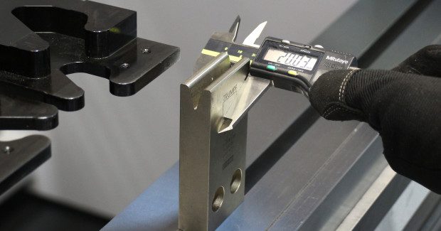
Once you have a few sample pieces in hand, measure the outside dimensions with your micrometer and record them. Be wary of tabs or other edge conditions that might throw off the measurement of your sample. Next, clamp your upper and lower tools into the press brake. Make sure to use a lower tool that is symmetrical. If your die has different width shoulders to either side of the V-opening, it is not a good tool for the test. Measure the total width of the tool front-to-back with your micrometer as shown in Figure 1. For example, the tooling used for this demonstration is sized in metric and is 25 mm thick. We will see in a moment why this measurement is important. Record this along with your test part size.
Next, you will use a press brake program to set the CNC back gauges. In the case of the 2 in x 2 in sample piece, I want to make a bend at .750 in length (outside dimension). By not bending the sample along the centerline, you can clearly see which end of the bent part was against the back gauges afterward. I set my program to put the gauge finger at exactly .750 in and started the program to move the back gauges into position.
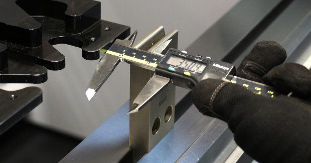
Now, with the lower tool clamped securely in the machine, measure from the front face of the lower die to the edge of the back gauge finger where the part should touch before bending. Measuring this way (as shown in Figure 2) allows us to make a very accurate determination of the distance from the bend (the center of the V-die) to the back gauge finger. This check ensures the distance from the centerline of the lower tool to the back gauge is correct. Aside from determining bend deductions, this is also a good way to verify the positioning accuracy of the press brake. The measurement that I want is .750 in plus half of the die width. In this case, the die width is 12.5 mm or .492 in so, if my back gauge is in the right position, the measurement should be 1.242 in from the front face of the die to the gauge finger.
APPLYING THE RESULTS
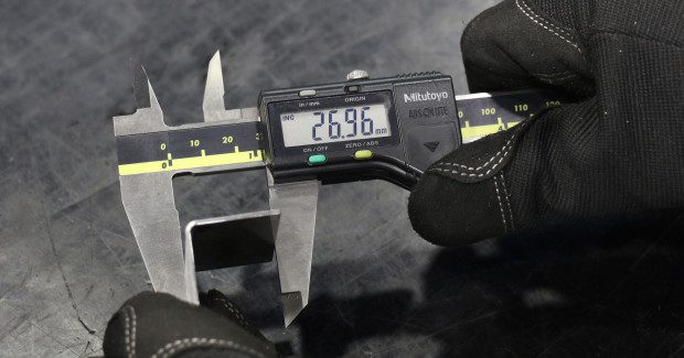
If your gauge passes the test, place your sample against the stop and make your test bend. Your finished angle should be as close to true 90 deg as possible so try a few test bends if necessary. Once you have a good 90 deg bend, measure the outside dimension of the bent flange with your micrometer as shown in Figure 3. Remember, the distance from the centerline of our lower tool to the gauge finger was .750 in so the outside measurement will be exactly .750 in plus the stretch factor of this material and tooling combination.
If my outside dimension measures .783 in, I now know that this material with this tooling will stretch exactly .033 in on each side of the bend at 90 deg. Taking this measurement back to the engineering end and applying to our flat pattern, you can be confident parts produced are dimensionally accurate right up to the limits of your fabrication equipment, and you can safely say that guesswork and rework have been removed from the process.
Subscribe to learn the latest in manufacturing.


Industry News