Programming Must-Haves for Successful Laser Tube Cutting
Quality software is the first step to precision tube component manufacturing. Knowing what to look for based on your programming needs will help determine the best solution for your shop.
Posted: December 21, 2016


Sheet metal parts and assembly programming is the lifeblood of manufacturing, an essential piece of the process that transitions a mere concept into a tangible product. Tubes are often the most difficult parts and assemblies to create, especially considering how the programming software for these tends to be highly complex. For maximum success and the greatest flexibility in elaborate tube component design, the software must provide basic tube profile information, intuitive commands, and specialty commands alike.
TUBE PROFILE INFORMATION
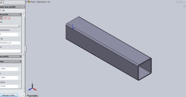
Software that clearly lays out basic tube profile information is critical to the success of the programmer in their quest to create quality items. Quality tube design software will account for the profile criteria of material type and wall thickness at the very least; however, this is not the only information needed. Round profiles, rectangular profiles, and various specialty profiles require additional and differing information to achieve the best results. As the profile shape changes, so does the required structural information. Round tubes are the most basic profiles and simply require a tube diameter dimension in addition to material type and wall thickness. Rectangular tube profiles (see Figure 1) are more challenging and will require parameters for height, width, and corner radius. Software that fails to properly account for these measures can result in inaccurate parts and potential machining collisions.
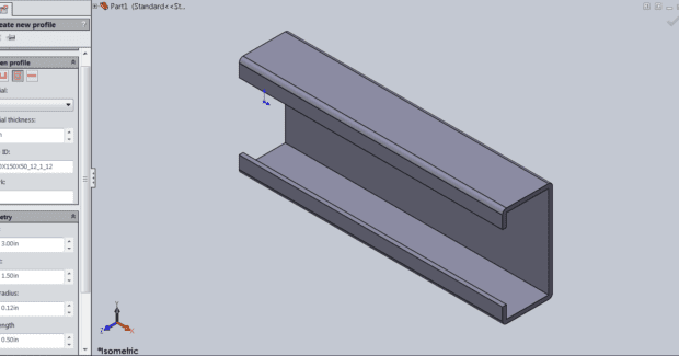
Specialty profiles are even more demanding and only software of the highest mark can be expected to account for the full range of variables needed for a perfect cut. Specialty profiles include the likes of C-channel, U-channel, D-tubes, and various other irregular profiles. Programming for such profiles requires software that can identify the key characters and dimensioning fields of its unique configuration. For example, software that allows for programming of C-channels (see Figure 2) should include dimensioning fields for height, width, edge radius, and side length. If a specialty profile is not available within a pre-selection field, look for software that will allow the programmer to draw the profile and extrude it to length. Once the profile is created and properly proportioned, intuitive commands should exist to expedite the process and alleviate manual application errors.
INTUITIVE COMMANDS
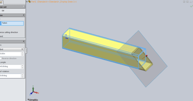
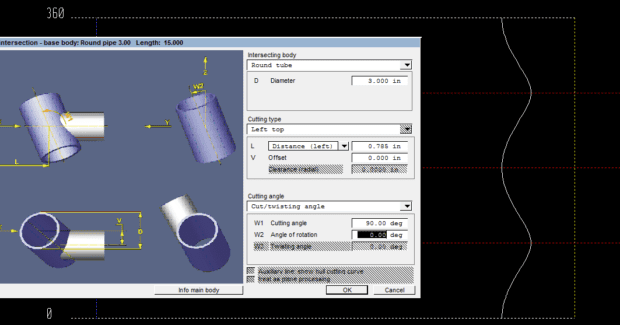
Intuitive commands are icons that exist within the software that enable the user to fulfill a programming process that would otherwise be laborious and/or highly difficult to perform accurately. Examples of intuitive commands include features such as attachments, insertions, fit-ins, fit-throughs, cornering, bending and plane cuts. While most software includes such options, those that do not will put the immense and often difficult task of implementing these options on the programmer. Choosing software with intuitive commands is a good start; however, it is imperative to remember that not all software is created equal. Review of the most simplistic and common of intuitive commands, the plane cut (see Figure 3), can shed some light on why it is valuable to examine the commands more closely before making a selection.
When utilizing a soft key for a plane cut, input fields for the cutting angle, angle of rotation, and whether it will be a full or partial cut are paramount. If these fields are not accounted for properly, secondary processes, such as welding the component to another fixture, could become more difficult than anticipated. While the plane cut is the most elementary of the intuitive commands, the importance of proper informational fields to programming achievement cannot be stressed enough. This can be seen with more complex concepts. Multiplex assemblies that require various tube profiles to be utilized together are made easy by well-designed software (see Figure 4). Commands such as fit-ins and attachments highlight this well. Attachment commands should include input fields for the intersecting body’s profile dimensions, the angle of the attachment, the cutting rotation, and twisting angle. Similarly, fit-ins require the same input fields as well as radial clearance.
SPECIALTY COMMANDS
While these intuitive commands are fairly common and essential to tube profile machining, some software packages also offer specialty commands that are less critical to the everyday user but still quite valuable. These specialty commands are found in premier software solutions and allow for highly advanced techniques to be implemented. This might be achieved by a simple click of an icon that activates advanced machining code, or by automatically creating complex contours that would otherwise be nearly impossible to draw. While these distinguishing features add an immeasurable value, they are not for every application or for every user. The bevel cutting command and the hooks/pegs command are excellent examples to help better understand these features.
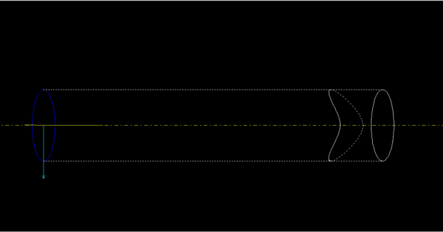
The bevel cutting command is used to create a beveled edge on a tube profile (see Figure 5). This edge is typically desired to create a flush, seamless edge on a pipe for welding purposes. Advanced software will allow a user to select an angled cut on a pipe and output beveling code for either the inside or outside edge of the cut. This simple one-click process can be the difference between a nearly undetectable weld seam and one that requires extensive filling.
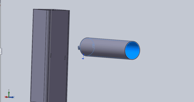
The hooks/pegs specialty command is utilized to create self-locking mechanisms on tube assemblies, for example, to connect a round tube to a square tube base (see Figure 6). By selecting the hooks/pegs command, the programmer can determine the number of pegs, the peg dimensions, and amount of play. The software will automatically create the peg contours on the round tube profile and the appropriate size slits for the square tube base. This drastically saves time and reduces programmer error.
Purchasing quality software is the first step to precision tube component manufacturing. Knowing what to look for based on your programming needs will help determine the best solution for your shop. At the very least, all manufacturers processing tubes should have software with basic tube profile information and some form of intuitive commands. Knowledge of specialty commands and their uses might lend itself to future endeavors. When purchasing software, remember it is the lifeblood of manufacturing. Take time in your research as it will support you through countless hours of production.
Subscribe to learn the latest in manufacturing.

Industry News