


An Introduction to Technical Cleanliness Inspection
Quality and characteristics of the product material, fitting tolerances, and overall cleanliness of a surface or particle load all contribute to the measurable technical cleanliness of automotive components, an integral factor in upholding rigorous requirements on emission reduction, fuel efficiency, long-term durability and regulatory standards.
Posted: December 22, 2017

The cleanliness of components is at the center of most industrial manufacturing processes, since these parts must be free of contaminants to ensure a high quality finished product. Technical cleanliness inspection involves quality control, process management, and manufacturing departments taking samples from the production line and utilizing particle extraction through filter membranes to quantify contaminants that may impact the performance, lifetime, and reliability of final products.
What are the basics of technical cleanliness? The growing complexity of today’s technical products, especially within the automotive industry, has resulted in an increasingly high demand for product reliability and quality assurance. Making the automotive industry that much more complex, manufacturers must consider requirements such as emission reduction, fuel efficiency, long-term durability, and regulatory standards. The durability and lifecycle of a finished product depend on a number of characteristics, all of which contribute to its measurable technical cleanliness:
- Quality and characteristics of the product material.
- Fitting tolerances.
- Overall cleanliness of a surface or particle load.
How does technical cleanliness affect a product’s reliability? Product contamination, which usually occurs during manufacturing but can also be the result of storage, cleaning, or handling, has a direct influence on a finished product’s reliability and its lifespan. The dangers of unclean surfaces or production liquids can range from function loss to product failure to complete breakdown. Residues on the surface of technical devices used in manufacturing and assembly processes can cause unreliable and/or poor device performance, downtime in production, or the waste of materials and energy. Large residue particles (sometimes called “killer particles”) may cause complete function loss. With the ever-decreasing size of system components, smaller residue particles can also cause catastrophic failures and lead to the breakdown of an entire end product.
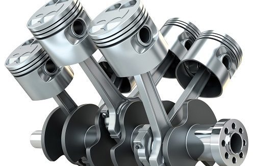
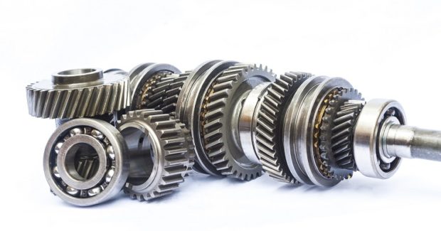
During automotive production, manufactured metal parts are processed, including cutting, grinding, and deburring. Serious, system-wide problems can occur if metal chips and other foreign matter produced during the manufacturing process are not properly cleaned and removed from critical systems (e.g., crankshaft bearing clamps, valve blockages, nozzles, injectors, filters, or electronic parts). The entire system is subject to failure if any part of the fuel system, braking system, hydraulic circuit, or electronics doesn’t meet cleanliness requirements.
For example, a brake caliper houses a piston that acts as a clamp to press the brake pad against the rotor, and the movement of the piston is essential to proper brake function. To help ensure that the piston functions properly, the area inside the brake caliper must be very clean. The piston unit is completely sealed to prevent contaminants from interfering with the action of the piston. This is especially important since a large number of contaminant particles are produced as the brake pad wears down. Cleaning is one of the most important steps in the caliper manufacturing process, and inspectors must monitor each part’s cleanliness to prevent metal chips from contaminating the caliper.
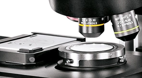
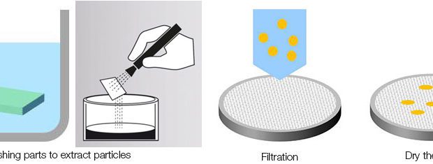
What is the technical cleanliness inspection process? Contaminant particles are first separated from the system or parts via a liquid shower or an ultrasonic bath. The washing rinse is then filtered through a membrane to extract the particles. The filter is clamped in a holder and dried for further analysis, then mounted on a microscope’s stage for image acquisition and examination. Since dedicated magnification can limit the camera’s field of view, larger particles might be split between two or more images. To ensure that they are only detected once, each particle can be described by different parameters. The most important of these parameters are the maximum Feret diameter and the equivalent circle diameter, both of which measure the particle’s length. Other particle parameters can be used to measure a particle’s area, shape, and reflectivity. These traits are used to recognize special particle families, like fibers and reflecting particles. Distinguishing between metallic and nonmetallic particles is based on the different behavior of the reflected light.
A particle detection process report is generated highlighting the size (typically the maximum Feret diameter) of each particle and categorizing them into different size classes to provide a better comparison of the measurements. Depending on the standard used and the filter being tested, the number of particles is normalized to a comparison value. Classification parameters and class division are defined in various international standards, but the automotive industry size classes are defined by minimum and maximum particle size. Each particle is placed in only one class. A typical standard with differential size classes is VDA 19.1:
- Class D: all particles where the maximum Feret diameter is larger than 25 µm but smaller than 50 µm.
- Class E: all particles where the maximum Feret diameter is larger than 50 µm but smaller than 100 µm.
- Class F: all particles where the maximum Feret diameter is larger than 100 µm but smaller than 150 µm.
Finally, the system generates a report containing all measurement results and data for the filter membrane.
What kind of system is required to conduct technical cleanliness inspection? Technical cleanliness inspection presents a number of unique challenges, including the need to regularly check results during inspection, view multiple particles simultaneously, revise results based on various standards, and quickly circulate results. One example of a system designed specifically to address these challenges – as well as to meet the cleanliness requirements of national and international directives such as VDA 19.1 and ISO 16232 – is the OLYMPUS CIX100 technical cleanliness inspection system, a dedicated, turnkey system for manufacturers that need to maintain high quality standards regarding the cleanliness of manufactured components. The OLYMPUS CIX100 system makes it easy to quickly acquire, process, and document technical cleanliness inspection data while maintaining the highest quality standards. User-friendly software workflows minimize user action and provide reliable data while enabling the detection of reflective and nonreflective particles and contaminants from 2.5 µm up to 42 mm in a single scan. While detecting metallic particles typically requires users to capture two individual images by rotating an analyzer 90 deg (a time consuming process), this system recognizes reflective and nonreflective particles in a single scan.
https://youtu.be/TyBFZHqBk_k
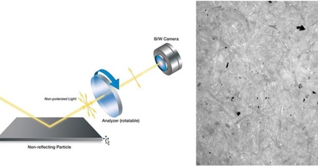
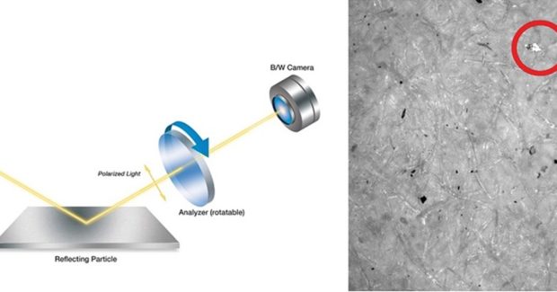
SEPARATION OF REFLECTIVE AND NONREFLECTIVE PARTICLES
The distinction between metallic and nonmetallic particles is made by determining whether particles reflect light or not (extremely important as metallic particles stand to cause much greater harm than nonmetallic particles). See Figures 1 and 2.
However, with the OLYMPUS CIX system, the incident light beam is also polarized. The polarization of one band of the light spectrum is changed using a retardation plate. As a result, the polarization of the incident light is different for different colors (see Figure 3).
All relevant data, including live and overview images, are displayed live on a single screen during the inspection to enable the operator to stop or interrupt the inspection if a filter membrane shows too many contaminants. The user can set the minimum particle size that the system detects by setting a threshold. Once this is established, the rest of the process is fully automated, enabling employees to engage in other tasks while the system does all of the work, thus eliminating the variability that is introduced when a human operator is manually taking measurements. The OLYMPUS CIX100 system supports major international standards used in the automotive industries, including:
- ISO 16232-10 (A) (N) (V)
- VDA 19.1 (A) (N) (V)
- ISO 4406
- ISO 4407
- ISO 12345
- NAS 1638
- NF E48-651
- NF E48-655
- SAE AS4059
Subscribe to learn the latest in manufacturing.


Industry News