


Making it Wrong to Make it Right
The world of a CAM programmer may seem idyllic: They build toolpath strategies in logical sequences, select cutters from a library, and calculate and simulate results on the monitor. But there are complex challenges when moving from the sterile programming office to the shop floor, where the theoretical process becomes real.
Posted: February 7, 2018


CAM technology actually has its roots in the 1950s, but modern CAM has developed more rapidly in the last 20 years with implementations on low cost and high performing personal computers. As computers became more capable, the size and caliber of problems solved with CAM also increased. Problems moved from 2D wireframe to 3D to 5-axis, and now also for more complex multi-axis and multi-task machines. About ten years ago, the goals of this technology were quite basic. Everything fell into two important categories: improve the programmer’s experience or improve the shop floor experience. One software release would have faster calculation time, an easier and more organized user interface, and new strategies to simplify programming. For the shop floor, better toolpaths would include less collisions (no collisions), more efficient toolpaths, toolpaths that produced longer tool lives and more.
In addition to computers, machine tools, machine control systems, and cutters (and coatings) were also improving. From these developments, manufacturing productivity increased and the price of manufactured components came down. In this phase of CAM developments, automation and knowledge-based machining also took an increasingly important role. Here we talk about tool database, feature recognition, and macro programming database. But now there is a revolutionary step in CAM programming coming to the forefront.
MODEL THE VARIABLES, MAKE IT RIGHT
Reducing engineering costs or making parts faster and with higher quality is surely a good thing. But the overarching goal is to make a part that is accepted by the customer. Many variables enter the scene when the programming world meets the shop floor. Machine tools may be aging and may have previously experienced a spindle crash and are no longer factory-aligned. Shop environment, such as room temperature, is not always controlled. Then there are practical tolerance issues: Tools may not be ground perfectly, or may be reground. Tools may not be set perfectly. Some tool holders have runout. Machine spindles may grow when running under load, and tool lengths can vary. Then add to all of this the realities of machining: a thin-walled surface may deflect, a long cutter may deflect, a worn cutter will not behave predictably.
Modeling these variables can be very useful to ultimately produce an accurate part. In a sense, it is akin to making a part wrong to make it right. There are attempts to model these situations, whether considering spindle warm-up each morning, probing to check tool length, or updates to controller offset tables. But the often-faced reality is that making a part to meet all tolerances and objectives is not easy. To achieve total part quality, additional modeling is needed, such as available in advanced CAM software including hyperMILL® software from OPEN MIND Technologies USA. This software needs capability and flexibility to make a good part because programming a part purely to the design model may not make the correct part. The examples below begin to create a new paradigm for how to make a better part. In one case a deformed model is programmed and machined, and in the other case the tool path was programmed intentionally with sophisticated offsets and blending algorithms to improve the part quality.
Production Example
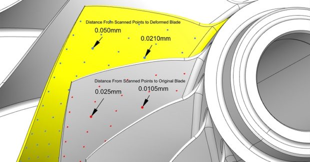
The first example is a turbomachinery compressor impeller. This is a complex part required to hold tight positional tolerance. It also requires low imbalances and a fine surface finish. A centrifugal compressor typically has a long leading edge surface and thinner sections near the shroud (outer contour), as compared to the hub. Industrial compressors are typically built to spec for each application. However, aero-engine components are manufactured in production quantities with a defined process to achieve needed quality standards. What happens? On the first article parts, the blade deflects. The area near the leading edge shroud may be oversized by 0.004 in (0.1 mm). But other areas near the hub and trailing edge may be correct or close to nominal size. The deviation map is not uniform.
The typical way to set up a consistent production process for these compressors is to make first article components. Measure the blade surfaces. The CAD model is then deformed according to the deviation map to compensate for deflection and other errors. This deformed model is then used for programming, and there are again deflections and other errors that create an oversized part relative to the deformed model, but an in-tolerance part compared to the actual part model (see Figure 1).
Mold and Die Example
The requirements of mold and die are considerably different than the aero-engine example. In these cases, specific dimensions near fillets are not usually critical to the part performance, but surface finish and blends in areas where cutters are changed are of the utmost importance. It can be very hard to obtain high quality blends, especially when wall or bottom surfaces are not machined with the same cutter that was used to reduce fillets. Typically, larger cutters are used to machine walls or bottoms. The small cutter required to form the corner radii can be used to machine entire surfaces, but this can greatly increase machining times. Using a small cutter over the entire surface would also result in too much wear, making it unable to complete an entire operation. A cutter change would also lead to a mismatch.
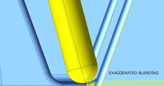
Often the smaller cutter has a short stick-out to be effective and then is programmed with 5-axis simultaneous or 3+2 indexed machining. With a different holder and stick-out, different technology values, and a generally different angle of attack, the chances of a clean blend are very low. To assure needed blends, mold makers often apply hours of manual benching processes. The benching does not leave uniform results. Additionally, skilled manual labor is not easy to find from new entrants to the workforce. A better way to approach this is to utilize CAM software routines that account for needed blending. The programmed surface is the actual design model, but compensation values are also specified to enable a smooth blend. An overlap distance and ramping offset are enough to guide the new toolpath (see Figure 2). This process has better results compared to a uniform allowance, which would make an undercut if aligned to a perfect match. The new remaining cusp between the wall surface and fillet surface is imperceptible. Manual finishing has been greatly reduced or eliminated.
https://youtu.be/rRDJNmo2Qrk
SUMMARY
Basically, by going through this check and balance (poka-yoke) process, programmers and machinists discover the best way to modify/make the best part. New turnkey CAM software solutions are invaluable for seamlessly addressing this process.
Subscribe to learn the latest in manufacturing.


Industry News