


What You Need to Know About Weld Anatomy and Joint Geometry
Are you wasting lots of time and money on welds that are larger than they need to be, particularly on thicker materials? Or dealing with inconsistent quality or increased crack sensitivity due to welds with improper dimensions? There are many different ways to design welds that strike the best balance between weld quality and productivity.
Posted: May 29, 2019

The anatomy of a weld is the structure of the weld itself, described in terms of weld legs, toes, throat and face. Each part not only contributes to the integrity of the weld, but also has an impact on other factors in the welding operation. Joint geometry is similar but refers to the dimensions of the weld joint itself, as opposed to the completed weld. When describing the weld joint geometry of a groove weld, for example, it is done so in terms of joint type, included angle, depth of preparation, root face and root opening. So why is it important to care about weld anatomy and joint geometry? Both can impact costs. Welds that are designed and/or welded to be larger than they need to be (overwelded) can be a significant waste of time and money, particularly as material thickness increases. Both can impact quality. Welds with improper dimensions may have inconsistent quality or increased crack sensitivity. There are many different ways to design welds to strike the best balance between weld quality and productivity.
UNDERSTAND WELD ANATOMY TO OPTIMIZE COSTS
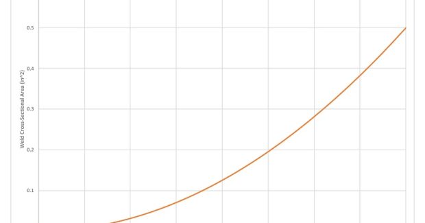
A larger weld joint cross-sectional area equates to greater weld volume and weight and requires an increase in filler metal consumption that results in higher weld costs. More important to the bottom line, a weld with a larger cross-sectional area takes longer to complete. While filler metal is roughly 10 percent to 15 percent of weld cost, labor and overhead are significantly greater, accounting for approximately 85 percent of the total cost. The size of the fillet weld is determined by the length of the fillet weld legs, but an increase in leg size does not lead to a 1:1 linear increase in cross-sectional area. Instead, the relationship between leg size and cross-sectional area is parabolic. This means that the effects of overwelding may seem insignificant when leg sizes are very small, but it can cause a significant contribution to weld cost as leg size increases.
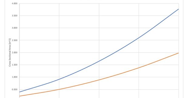
Using a double-sided joint configuration – such as a double V-groove as opposed to a single V-groove – can significantly reduce the amount of time and filler metal required to complete a weld, especially on thicker material. However, these joint configurations do require welding from both sides, which may not be possible, practical or cost-effective in all applications.
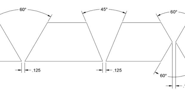
Selection of bevel/included angle also has significant influence on weld cross-sectional area, cost and quality. For many joint designs, bevel angle and included angle are not interchangeable terms. Bevel angle is the angle at which a single plate is prepared, while included angle is the total angle formed by the preparation of both plates. For a single-bevel groove weld, the bevel angle is equal to the included angle, but for a single V-groove weld, this is not the case. If both plates were beveled at 30 deg angles, the included angle would be 60 deg. Be aware that larger bevel/included angles equate to higher weld cross-sectional area, weight and cost, so it is advantageous to keep them as small as practical, ensuring that weld quality can be maintained consistently (see Figure 1).
UNDERSTANDING WELD METAL ANATOMY TO IMPROVE WELD QUALITY
The included angle selected should allow for obtaining good fusion throughout, depending on the welding process and parameters chosen. Be aware, however, that further increasing bevel/included angle beyond this point provides virtually no increase in component strength despite the increase in cross-sectional area. In many cases, increasing bevel/included angle can result in increased distortion and/or residual stress. Included angles that are too narrow will make consistently achieving good fusion throughout the cross-section difficult. Excessive dilution can also result from an excessively small included angle, which can lead to crack sensitivity when welding certain alloys, such as 6xxx series aluminum alloys. Determining the optimal included angle requires striking a balance between ease of welding and welding economics.
The strength of a fillet weld is determined by the effective throat size, which is different than the theoretical throat. The theoretical throat is the distance from where the two plates come together [the theoretical root] to where the face of a flat fillet weld would be. The effective throat is defined as “the minimum distance from the fillet weld face, minus any convexity, and the [actual] weld root.”1 This definition reinforces that convex welds are wasteful and should be avoided, as the additional weld material does nothing to help improve weld strength. Conversely, it is often critical to avoid concave welds, since these welds have smaller effective throats; these concave welds will not be as strong as the design intends. For fillet welds with a flat contour, the effective throat tends to be larger than the theoretical root due to the penetration of the welding process used. Welding processes providing deep penetration may achieve the intended weld strength with smaller weld leg sizes due to the effective throat being the same as a weld having less penetration into the weld root.
It’s important to consider aspect ratio in order to help prevent solidification cracking. Aspect ratio, similar to that of a TV or computer screen, is a comparison between depth and width of a weld pass. A weld pass that’s deeper than it is wide increases the risk for solidification cracking, also known as hot cracking. A weld pass that is twice as deep as it is wide is particularly susceptible.
It’s also important to consider the reentrant angle when attempting to maximize the fatigue life of welded components. A high reentrant angle does not transmit stress through the weld as effectively as one with a lower reentrant angle. As a result, the shape of the weld toes can influence the weld’s fatigue life. The most cost-effective way to improve fatigue life is to adjust work and travel angles, welding parameters and technique to produce a weld with the optimal contour the first time. Remember, like any aspect of the welding operation, understanding weld anatomy and joint geometry can be helpful in maintaining appropriate weld quality, productivity and profitability.
STANDARD VS. NON-STANDARD TERMS
There is a lot of terminology, both standard and nonstandard, that can describe weld anatomy and weld joint geometry. It’s important to be familiar with both sets of terms in order to communicate about a weld more effectively and prevent misunderstandings. The American Welding Society (AWS; Miami, FL) “A3.0M/A3.0: Standard Welding Terms and Definitions” book includes a collection of over 1,400 standard and nonstandard terms. Standard terms are preferred by AWS over nonstandard terms, although the latter are not necessarily incorrect. In some cases, nonstandard terms are the most common in industry, but it’s important to be familiar with both to maintain effective communication with whomever you may come across. For example, root opening is a standard term and gap is a nonstandard term, but both mean the same thing. Common weld joint designs are best described with letters:
- Standard terms: “V,” “U,” and “J” weld joints.
- Nonstandard terms: “K,” weld joint (a double-bevel groove weld) and “X” (a double V-groove weld).
Being familiar with weld symbols can be an effective method of communicating (beyond standard or nonstandard terms) the desired geometry of the completed weld and its preparation. Weld symbols can be found in “AWS 2.4: Standard Symbols for Welding, Brazing, and Nondestructive Examination.”
References
1. American Welding Society, A3.0M/A3.0 Standard Welding Terms and Definitions, 12th Edition. (Miami, FL: AWS, 2010).
Subscribe to learn the latest in manufacturing.


Industry News