


Weld Functions You Should Be Using
Welding and fabrication are complex processes that can greatly benefit from robotic automation. While each application will differ in complexity, the consistent and effective use of certain weld functions can improve quality and enhance productivity while decreasing costs.
Posted: September 3, 2019


Regardless of the manufacturing industry, company size or part dimensions, the general purpose of robotic welding is the same: to produce high-quality welds in the least amount of time. While achieving this goal may present a bit of a learning curve when it comes to reaching optimal weld quality in the preferred cycle time, the following weld functions are available to help you take your weld process to the next level:
COLLISION DETECTION
A robot is designed to sense motor torque on its axes. If an abnormally high torque is encountered, the robot can shut down, potentially avoiding collision with tooling and subsequent damage. The torque level for an alarm is programmable, allowing the user to set it for an ideal threshold, just above the normal range it will see during a program. Of course, a higher torque would mean the robot hit something, causing it to decelerate. The use of “clutches” or deflection mounts for torches and other tools will allow the tool to deflect upon impact while the robot stops. This can help reduce damage to the tool.
TOOL CENTER POINT (TCP) INSPECTION
The Tool Center Point (TCP) dimensions define the desired control point from the end of the robot flange. The robot will reference this dimension as it moves between program points, often interpolating the motion to maintain a straight path or circular path between program points. For a welding robot, the TCP is at the end of the welding torch with the desired length of wire electrode extension. Programmers create the weld programs to make sure this point is properly positioned in the weld joint. Robot manufacturers may have gauges or devices to measure the torch position during production. This can help to verify the robot’s torch is properly aligned and may assist in realigning the tool coordinates if they are off. Torch manufacturers offer gauges to inspect torch necks for proper alignment to help maintain a consistent TCP. Users can even reference something as simple as a punch mark on a tool or fixed object in the workcell to quickly identify if the torch tip has varied from normal position.
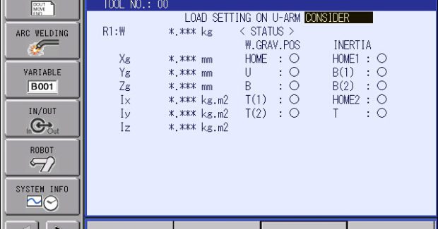
TOOL WEIGHT AND GRAVITY MEASUREMENT
The Tool File contains the information for Tool Center Point dimensions, which are critical for circular and interpolated motion, but there may also be settings for tool weight. Robot manufacturers may have motion algorithms that use kinematic information for the tool to optimize the acceleration and deceleration of the robot, improving cycle time. Be sure to verify proper moment and inertia for the torch if it is identified as a robot setting. Torch manufacturers are usually able to provide this information.
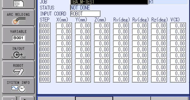
PAM (POSITION ADJUSTMENT MODIFICATION) FUNCTION
This allows program points to be adjusted during Playback mode without stopping production. It does require some preparation; knowing the step numbers for weld locations in the program and the orientation of the points in order to specify a numeric offset. Creating a “map” of the weld program – noting the sequence and location of program points – is always a best practice for documentation and supporting a workcell with multiple personnel. Up to ten points can be offset at a time in X, Y and Z directions relative to a specified frame. Travel speeds can also be adjusted by entering a percentage (80 percent to 120 percent). The updates can be made immediately in Teach mode or take effect on the next cycle in Play mode.
WELD LINE SHIFT FUNCTION
This is another method of introducing offsets to weld locations to account for stamping runs or other production variations. It includes a shift amount in relation to the joint coordinates (upper leg or lower leg) and is set in the Arc Start File. It will shift all weld locations that use that Arc Start File, and it will shift all points between the ARCON and ARCOF instructions. There is a Shift Cancel Function under Utility Menu if the program needs to be verified without the shifted amount applied.
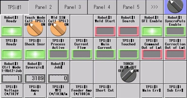
PROGRAMMABLE LOGIC CONTROL AND HMI PANEL DISPLAY
Robot manufacturers have incorporated programmable logic control (PLC) programs into the robot controllers. This runs in the background to the normal motion tasks that users would program with the robot’s teach pendant. This “ladder logic” is used to turn on outputs or read inputs from peripheral devices connected to the robot. The capability and capacity of this programming logic has grown to the point that the robot controller can handle the control of all devices in a cell. The robot teach pendant can also serve as a display for the IO status of peripherals in the cell; such as weld equipment, part counters or tools. This can help reduce costs of integration and simplify troubleshooting.
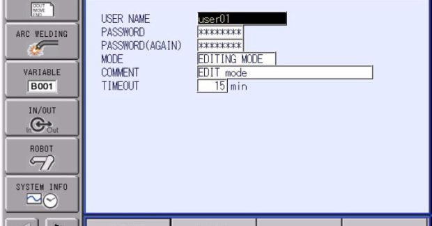
LOGGING AND PASSWORD FUNCTIONS
A long-time tip for programmers has been to keep a log outside the robot cell where technicians can note “what” and “when” they make changes to the robot programs. Robot controllers now often keep an internal record, or log, with date and time stamps, noting what has been changed in the program. This can be particularly helpful for plants with multiple shifts when trying to figure out if something changed. Users normally have the ability to select the types of events they want logged, and there is normally a finite number of events that can be recorded; typically spanning a day or two of production. Robot controllers have the capability to provide user names and passwords for individuals to administer their security rights to make changes on the system. While the use of individual security levels can help prevent plant-wide abuse of a global security password on the robot, this may also lead to delays responding to an alarm condition until the proper person logs on with their credentials. When combined with the above Logging Function, it will record the User ID logged on during the recorded event.
UNDO FUNCTION
This is an editing function that may be enabled. It will keep a temporary memory of changes that allows a programmer to restore some data that may have accidentally been deleted and needs to be recovered. Those who have found themselves saying “oops” while programming, probably wished they had this enabled.
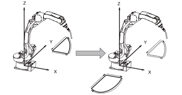
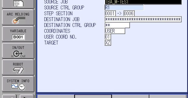
PARALLEL SHIFT AND MIRROR SHIFT OF JOBS
These functions under the Utility Menu can reduce programming times, copying jobs to multiple locations or from side A to side B of a positioner. Parallel Shift allows a range of points to be selected to shift, so the start and end can remain the same, or just sections of the program can be offset. A Teach Setting makes it easy to measure a shift amount by recording the difference from original taught position (source) to the new desired location (destination). The Mirror Shift Function is a utility with multiple robot systems that allows a Job to be copied from one robot to another, reversing the wrist orientation. This is convenient for symmetrical parts where the robot is working on right hand and left hand sides of a part that are identical, except mirrored orientations.
Welding and fabrication are complex processes that can greatly benefit from robotic automation. While each application will differ in complexity, the consistent and effective use of certain weld functions can improve quality and enhance productivity while decreasing costs.
Subscribe to learn the latest in manufacturing.


Industry News