


READING THE DROP CUT
Step-by-step instructions for perfecting your plasma cutting technique. Similar to how an archeologist can read the history of a canyon wall, an experienced plasma cutting operator can take one look at the surface and tell you what went right, what went wrong, and how to correct your mistakes.
Posted: December 31, 2019


Similar to how an archeologist can read the history of a canyon wall, an experienced plasma cutting operator can take one look at the surface and tell you what went right, what went wrong, and how to correct your mistakes.
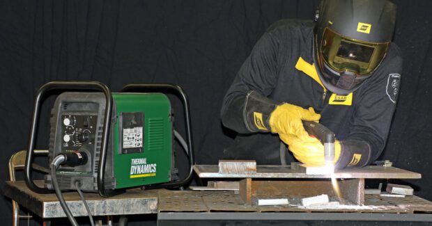
Their ability starts with understanding the plasma jet is a swirling, three-dimensional, superheated column. With temperatures up to 30,000 degrees F, the plasma jet blasts through any metal that conducts electricity. After knowing the nature of the tool, next comes understanding how to use the tool—controlling travel speed, torch height, torch angle, and torch manipulation—to produce a good cut that enables the part to move to the next fabrication step with as little additional work as possible.
DEFINING GOOD
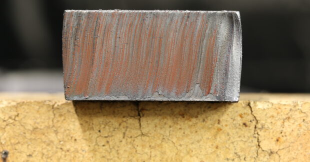
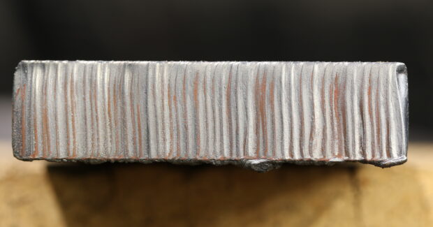
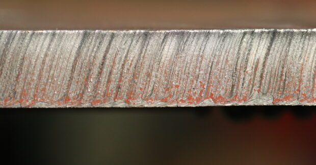
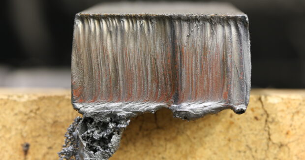
The swirling plasma jet leaves striations, or “drag lines,” on the cut surface. A good cut has fine, consistent, and parallel drag lines from top to bottom. They may be perpendicular or angled by up to about 15 degrees, with the variability caused by a combination of travel speed and torch angle.
A good cut also has a square top edge, no top splatter, and very little dross on the bottom of the cut. Dross results from metal that melted and re-solidified instead of being ejected by the force of the plasma jet. A small amount of dross is acceptable.
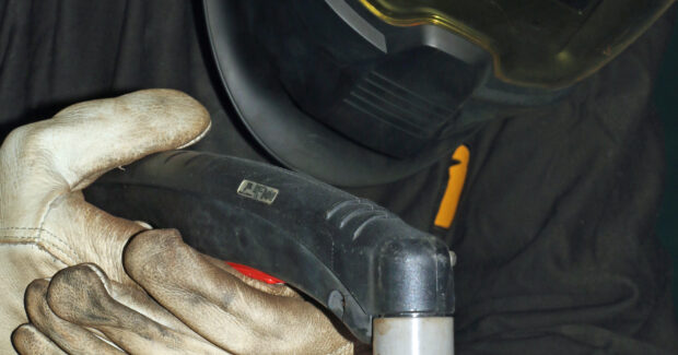
Good cuts result from good mechanics. For cutting with an exposed tip, hold the torch 1/16 inch to 1/8 inch over the top of the workpiece (or use shield cap that provides a built-in standoff). Because an unsteady hand will appear as inconsistencies in the drag lines, brace yourself properly; trace the cut path to ensure you can move freely before triggering the torch. A torch with a consumables design that offers a clear view of the cut path can help.
TRAVEL SPEED
When cutting, a proper travel speed causes the plasma jet to exit the bottom of the workpiece at a 5-to-15-degree angle. Moving too slowly causes the arc to “over-burn” the kerf (cut width). At a minimum, this can cause fit-up issues. In addition, dross builds up on the bottom of the cut because the arc burns more metal than it needs to, so the cut requires more cleaning time.
Excessive travel speed makes sparks fly in all directions. Because the arc hasn’t fully penetrated the plate, the molten metal has no place to go. Below the plate, it shoots out a rooster tail of sparks at an extreme angle, which will be evidenced by J-shaped drag lines. In all probability, you won’t sever the metal and will need to re-cut the piece.
TORCH POSITION
During the cut, hold the torch mostly perpendicular. That said, it’s OK to tilt the top edge of the torch 5 to 10 degrees toward the direction of travel (a “drag technique” if you want to equate it to welding).
However, too much tilt extends the arc more than necessary, and the arc might struggle because you’re trying to cut through more material than required. J-shaped drag lines and excess dross can also indicate too much of a tilt. Straightening the torch will create a cleaner cut, as well as increase travel speed by as much as 20%.
Other cut imperfections include top-edge rounding, likely caused by holding the torch too close to the plate. The excess heat digs into the material and rolls over the edge of the cut.
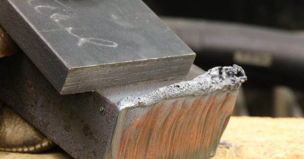
PAUSE AND ROLL
If you’re familiar with the sounds of swearing while swinging a hammer to slam off a part hung up at the beginning or end of the cut, correct the problem by moving the torch like pendulum on a grandfather clock.
Assuming a left-to-right travel direction, use this order to make a drop cut. Position the top of the torch over the edge of the plate, point the torch at the 7 o’clock position, trigger the arc, and roll the torch to the 6 o’clock position. Pause for a second on the edge of the plate, allow the arc to penetrate through to the bottom of the material, and then move forward. The “roll” ensures you sever the plate’s top edge and the pause ensures you catch the bottom corner.
Exiting the cut requires reverse the technique. When the top torch of the torch has reached the end the plate, remember that the plasma jet is lagging by 5 to 15 degrees. If you’ve been using a slight drag angle to the torch, roll the torch to a perpendicular position and pause for a moment to allow the plasma jet to catch up. Finish the cut by rolling the torch toward the 3 o’clock position to sever the top corner, then enjoy the sound of a clean drop cut.
Kris Scherm is global manual plasma business and product director for ESAB Welding & Cutting Products in Annapolis Junction, MD. Email kristofer.scherm@esab.com.
Keep Reading From Our Metal Forming & Fabricating Feature:
TOOTH IMPROVEMENTS INCREASE BANDSAW BLADE EFFECTIVENESS
Less prone to chipping when used for interrupted cuts and less expensive than carbide, tools made from M42 molybdenum-series high–speed steel alloy with 8% cobalt shorten cycle times by facilitating higher cutting speeds. Featuring a powdered metal M42 edge for harder teeth, the 3851 Sandflex Cobra bandsaw blade from Bahco (Kenosha, WI) provides smooth, precise cuts for general-purpose and production-cutting applications.
TUBE-SAWING SYSTEM WITH AUTOMATIC CHANGEOVER
BLM Group USA’s (Novi, MI) TS72 universal cold sawing CNC system for cutting tubes, bars, and profiles features an axis-control function that enables automated changeover for nonstop, unattended production. Particularly well-suited to small batch sizes, all adjustments and cutting parameters – material, blade type, and tube dimensions – are automatic to eliminate downtime.
LARGE ABRASIVE CUTTER AND MEDIUM SECTIONING SAW
Two saws from Buehler (Detroit) provide consistency and repeatability in cutting production samples, saving preparation time in the quality control or inspection laboratory.
RECONFIGURED BANDSAW BLADE LINE
Simonds Saw (Fitchburg, MA) has stopped making Dieband, Blockbuster, and Broadband, IC Enduro, and X51 bandsaw blades and is replacing them with four new bimetal products.
INCREASE MILL AND LATHE PRODUCTIVITY
The AF50 Autofeed Bandsaw from Tormach (Waunakee, WI) cuts multiple parts with automatic workpiece positioning.
INTERNATIONAL APPLICATION SUCCESS-OPTIMIZED CUTTING PROCESSES
Daniel Caprio has more than 15 years of experience in custom cutting and machining. His company, Cap Coupes Services in north-central France, does custom sawing, prepares and machines test pieces, and provides metallurgical expertise for customers in the aeronautics, aerospace, nuclear, medical, and petroleum industries.
Subscribe to learn the latest in manufacturing.
Industry News