


Measure Twice, Weld Once
Pre-build calibration is critical to part quality for metal additive manufacturing, and the process is easier than ever.
Posted: July 8, 2021


ADDITIVE MANUFACTURING
BY ZACH MURPHREE
Conversations around quality in metal additive manufacturing (AM) often focus on the flashy application of high-frequency, in situ, real-time monitoring systems and the neural networks or machine learning required for map-reduction of the mountains of data generated.
There is, however, an often-overlooked aspect of consistently making high-quality parts: calibration.
Calibration ensures a parameter being measured correlates to some agreed-upon value that falls within the limits of what would make a good manufacturing process. It’s an essential component of qualifying parts and processes for acceptance in almost all critical industries served by AM; for example, 3D printing.
Industry-specific standards are still evolving for metal AM, and many standards organizations (ASTM, SAE, AWS, API, etc.) are working on developing or refining their documents. In October 2017, the National Aeronautics and Space Administration (NASA) became one of the first organizations to publish guidelines with the Standard for Additively Manufactured Spaceflight Hardware by Laser Powder Bed Fusion (LPBF) in Metals (MFSC-STD-3716) and accompanying Specification for Control and Qualification of LPBF Metallurgical Processes (MFSC-SPEC-3717). Both have served as a foundation for other organizations and standards bodies, with many requirements for confidence in printed part quality – including calibration – having flowed down to the newer standards.
According to MFSC-SPEC-3717, “Calibration is effective only when maintained continuously. For pragmatic reasons, confirming calibration is not feasible on a pre-build basis. This time-based calibration interval is set as a compromise between production efficiency and process assurance.” In other words, the inability to calibrate an AM machine before each build forces manufacturers to choose between production efficiency and quality assurance.
While that may have been the case in 2017, consistent pre-build calibration isn’t only feasible; today it is a reality. Available on next-generation systems, this capability is helping metal parts manufacturers maximize production efficiency and process assurance simultaneously rather than forcing them to sacrifice one for the other.
Calibrating Optics: Right Place, Right Time, Right Power
The optics in a metal AM system include one or more lasers and related equipment. They’re critical to the LPBF welding process, in which very thin layers of metal powder are melted, one on top of another, to produce a part. Measured in microns, each layer is generally thinner than the diameter of a human hair, and there can be tens of thousands of layers in any given part.
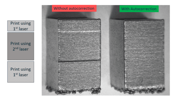
This is why calibration is so key. If a laser isn’t pointed in the right place with the right power and moving at the right speed, quality will likely be compromised. The risk is compounded on multilaser systems, where the calibration must also be consistent between individual lasers.
MFSC-SPEC-3717 specifies several metrics, including laser focus and alignment, that must be calibrated at least every 90 days for the process to remain qualified and parts labeled as conforming. NASA doesn’t specify how these metrics are to be calibrated, but concedes that “lasing purposeful markings into a flat, solid plate and evaluating the markings against metrics (based upon past performance) may provide sufficient evidence of scanner head health.”
This calibration method is standard practice, but it’s time-consuming and carries a substantial risk of inconsistency. It’s almost entirely manual, which means there are many inherent sources of variability. It continues to be used, however, because AM equipment developers haven’t had access to better methods.
To calibrate laser focus, for example, many machine manufacturers call for placing an anodized aluminum plate into the build chamber and setting it to the same height on the build plane as where the material would be printed (remember, microns matter). Lines are burned into the plate and then taken out and measured to determine which track is the smallest in diameter, thereby indicating the focus of the laser.
Similarly, laser alignment is determined by burning a series of lines onto an aluminum plate or thermal paper. The results are sent, sometimes physically, to a third party that uses an optical coordinate measuring machine (CMM) to analyze them, generate a calibration file, and send updates back to the field-service engineer for installation. More than one iteration is sometimes required, which adds significantly to calibration time. This process often takes a day or more to complete, and such non-productive time can be a significant drag on cost-of-ownership for such an expensive piece of equipment.
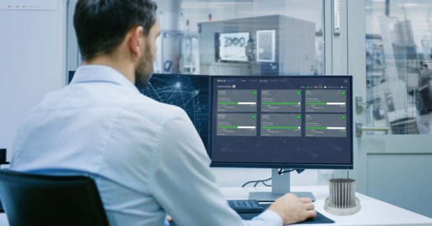
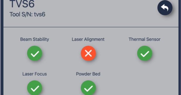
Today’s machines, however, don’t have to be taken off-line to be calibrated. They automatically measure a variety of metrics — beam stability, laser alignment, and focus — just before initiating the printing process. Rather than burning lines on aluminum plates, the end user runs optical calibrations with the push of a button and doesn’t need external measuring equipment such as power meters or beam profilers.
Equally important, this automated process captures a wealth of data that’s not available using manual calibration methods. This data is used to update the system’s calibration tables in real time and make sure a part is being manufactured to specifications. It can also be compiled over time for use in statistical process control (SPC) programs and other quality management systems.
Calibrating the Powder Bed: Not Too Thin, Not Too Thick
Calibrating the quality of the powder bed is also key to part quality. Thickness and uniformity must be precise to ensure the lasers melt each layer properly. If the powder bed is too thick, the layer may not melt completely and cause lack-of-fusion porosity. If it’s too thin, the metal may become overheated and can be vaporized in the melt pool. Either result can have a very negative effect on the part’s mechanical properties. Proper calibration is essential to delivering accurate layers of powder which, provided the optics are also calibrated properly, yield properly welded layers of metal.
Unlike its 90-day optics-assurance guidelines, NASA requires powder bed quality to be calibrated every 180 days. But six months is too long to wait to recalibrate, as a number of things can go wrong with the recoating process on any given layer. Much like a windshield wiper leaves streaks when it becomes worn, the recoater may become nicked or damaged, causing it to leave streaks in the powder bed.
Although it’s a critical metric, traditional AM systems can’t quantitatively measure powder bed quality and status. They may take pictures of the powder bed and then do a qualitative analysis of it, but this doesn’t provide real-time status.
Today’s machines, however, confirm the recoater is doing its job before and during each and every build. This capability hinges on height-mapper metrology systems, which essentially measure the powder bed topology to a resolution of 15 microns in the Z-axis and 100 microns in the X- and Y- axes. This truly quantitative measurement ensures the layer being delivered by the recoater is within specifications for thickness and uniformity across the build plane.
Pre-Build Calibration Ensures Part Quality Worthy Of Mission-Critical Manufacturing
The most obvious benefit of pre-build calibration is identifying problems before they affect product quality. Parts created using AM processes are not inexpensive. In fact, they can be quite costly and take considerable amounts of time to manufacture. Quality escapes become more expensive the farther down the workflow they’re discovered, so it’s important to catch them early — preferably before printing.
If calibration only occurs every 90 or 180 days, a problem may not be detected until after significant post-processing and even final delivery of parts. If a laser is out of focus or alignment, laser power isn’t correct for a job, or powder is being laid down too thick or unevenly, an entire batch could be headed toward the scrap heap at a cost of hundreds of thousands of dollars.
A second benefit is that calibrating the critical parameters of an AM system before each build generates a great deal of data that can be used to develop SPC control around a variety of metrics. By collecting data before each build on optical system status and powder bed quality and other parameters, it’s possible to see how the system is performing over time and, by seeing something that is trending out of specification before it actually reaches a control limit, to predict when the machine might need preventive maintenance.
The bottom line is that more frequent and detailed calibrations produces higher-quality 3D-printed products, and that the new generation of machines makes the process fast and user-friendly. Improved calibration addresses a key concern NASA has had with using LPBF technology as, in MFSC-STD-3716, the agency writes, “The largest latent risk… lies in the limitations to verify individual part integrity.” The ability of next-generation AM machines to perform a calibration before every single build is paving the way to acceptance of metal AM as the standard for a variety of mission-critical applications.
Subscribe to learn the latest in manufacturing.

Industry News