


Improving Tube Welding with Laser Inspection
Laser weld inspection systems using 3D imaging can improve productivity and quality control of ERW and HFI tube welding by working in conjunction with other NDT testing.
Posted: December 21, 2021


MEASUREMENT & INSPECTION
By Cameron Serles
Non-destructive testing (NDT) of welded tubes has been implemented as part of the standard fabrication quality assurance and control processes for some time. The traditional NDT techniques most widely used in tube mills are either Eddy Current Testing (ECT) or Ultrasonic Testing (UT). Both methods allow for in-line inspection of formed and welded tubes and pipes, capable of finding a number of welding defects and discontinuities. However, they have some inherent limitations including:
- Sensitivity to external conditions that can influence the precision of the measurement
- A relatively large number of probes that have to be used for obtaining reliable data
- The probes must be in direct contact or in proximity to the pipe surface, which makes them prone to wear or damage
- The overall cost and complexity of equipment set-up and inability to detect or classify some specific weld defects
While NDT equipment can provide significant benefits, they cannot detect all the defects that fabricators would like to detect on a tube. A laser weld inspection system using 3D imaging can help to find additional quality defects to complement NDT testing. In particular, it can better monitor the weld bead geometry right after the weld box on ERW/HFI tube mills, providing operators with valuable information about the weld profile to get early warning of forming or welding issues that are moving out of control, allowing operators to make adjustments before defective product is made.
HOW IT WORKS
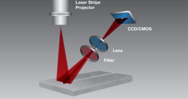
A laser weld inspection system projects a laser line across the weld bead and a camera looks at that line from an angle to extract shape information of the tube and bead surface. The result is a magnified profile of the weld bead scribed by the laser line as an accurate representation of the tube surface. This profile is similar to the surface that the operator would see when looking at a micrograph of a weld sample.
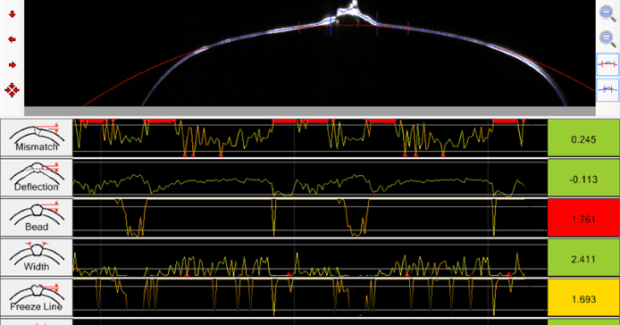
In software, the system overlays the profile of the ideal shape of the tube to help the operator visually compare it to the actual tube weld bead profile. Measurements can be made automatically as to how closely the tube matches its ideal shape. During production, the system can create time-based logs of a variety of measurements to give operators a quick visual reference of how the production is running.
The usefulness of a laser weld inspection system depends on the capabilities of its software to provide operators with meaningful, quickly understandable quality information in a simple format. Rather than spending time deciphering complicated data, operators can quickly interpret information presented onscreen and adjust mill parameters as needed.
Laser weld inspection systems should ideally use algorithms to turn the huge measurement data streams into simple visual indicators (e.g., sliders, on-screen alarms or light alarms) that make it easy for operators to see at a glance whether their process is in control.
Alarm limits for each bead measurement should be programmable and set by operators based on the desired tolerances. When any measurement exceeds the pre-defined tolerance limits, an alarm is raised. These alarms don’t indicate specific problems, but they do let operators know that the process is out of control, and the relevant section of tube can be spray-marked for further evaluation by quality-control staff.
THE SETUP
Laser weld inspection systems offer measurement accuracy as small as 7 microns per pixel. One size doesn’t fit all — the system must be selected to each mill based on the mill speed, welding type and product requirements.
Once implemented, mill operators, quality control/assurance staff, and production supervisors work together to determine the optimal settings to implement for each product type. Once the settings are determined for a particular product, an operator is able to store the settings to use again at some point in the future. This provides for more efficient product change overs and set-ups.
Laser weld inspection systems — such as the Xiris WI-2200 Weld Inspection System — can improve productivity and quality control of ERW and HFI tube welding by working in conjunction with other NDT testing. However, proper equipment selection, installation, tolerance adjustment, and maintenance are required to take full advantage of this technology.
To learn more about laser weld monitoring systems, visit www.xiris.com/weld-inspection-systems.
Cameron Serles is the president of Xiris Automation Inc. Email sales@xiris.com.
Subscribe to learn the latest in manufacturing.
Industry News